- 16 -
No.EX※※-OMW0011-B
3.2. Wiring
Caution
・ To prevent damage, all voltages to the SI Unit must be turned off (i.e. de-energized) before the
modules are installed or removed.
Wire the grounding cable, the PROFINET cables and the power cable.
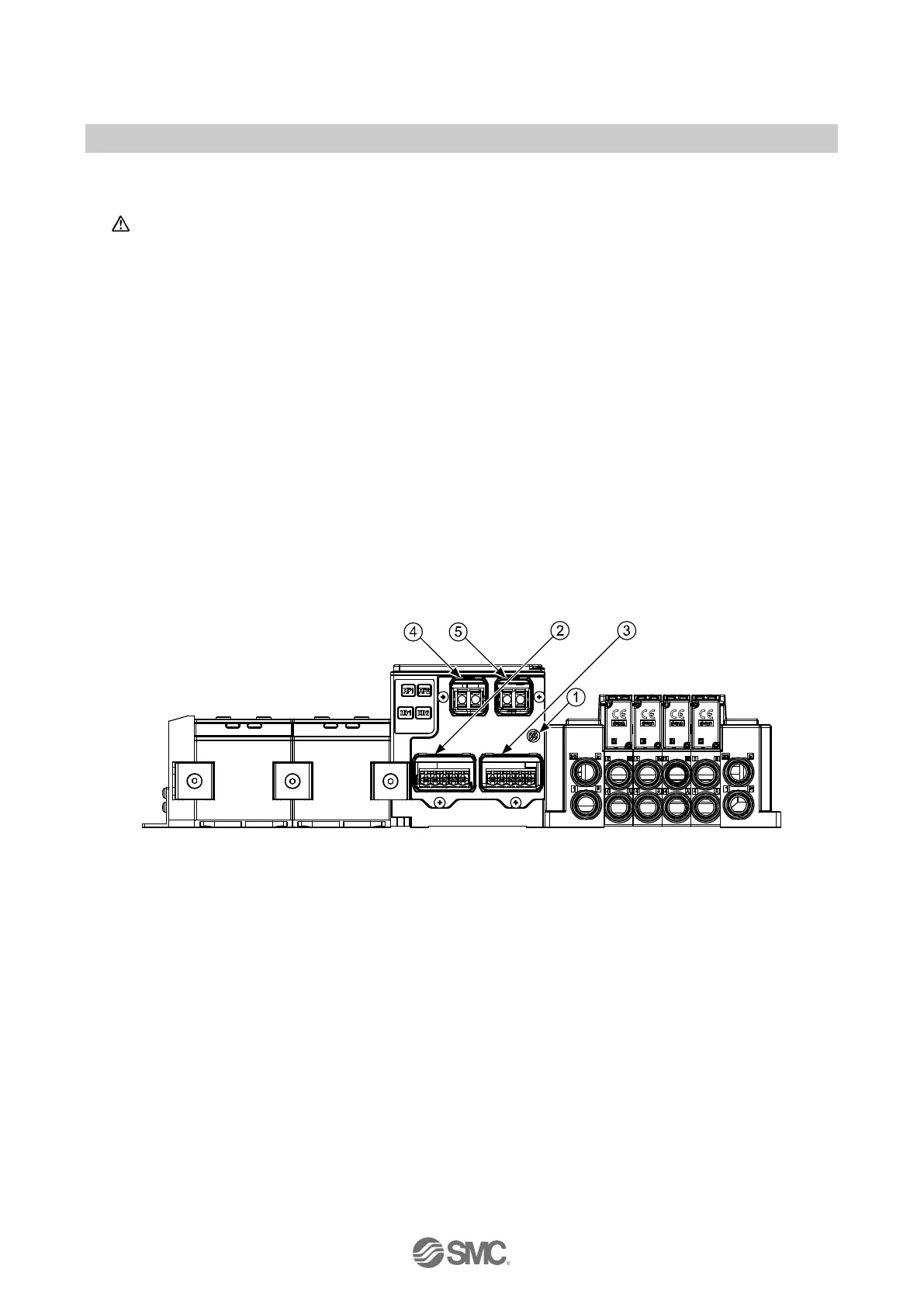
EX245-SPN1A
① M4, FE terminal screw (torque = 0.7 to 0.8 N•m)
② Push Pull connector (24 Volt), Power connection (XD1)
③ Push Pull connector (24 Volt), Power connection (XD2)
④ Push Pull connector (SCRJ), PROFINET connection Port1 (XF1)
⑤ Push Pull connector (SCRJ), PROFINET connection Port2 (XF2)
EX245-SPN2A
① M4, FE terminal screw (torque = 0.7 to 0.8 N•m)
② Push Pull connector (24 Volt), Power connection (XD1)
③ Push Pull connector (24 Volt), Power connection (XD2)
④ Push Pull connector (RJ45), PROFINET connection Port1 (XF1), Port type: MDI
⑤ Push Pull connector (RJ45), PROFINET connection Port2 (XF2), Port type: MDI-X
Fig. 3-4 Screw and connector allocation (EX245-SPN1A/SPN2A)
 Loading...