- 58 -
No.EX※※-OMW0011-B
9.3. Wiring
Caution
・ To prevent damage, all power for the SI Unit and modules must be turned off (i.e. de-energized)
before the modules are installed or removed.
・ For a protection rating of IP65 to be ensured, all covering caps must be screwed down correctly
after wiring and setting have been performed.
・ For a protection rating of IP65 to be ensured, sockets that are not used must be fitted with the
Seal cap.
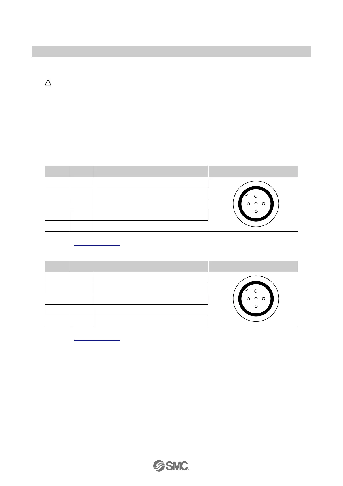
Pin allocation of the M12, 5 pins socket connector as shown in the following table:
Table. 9-1 Pin allocation of the connector for EX245-LA1 (Class A)
Pin Signal Description / Power source View of connector (module side)
1 L+ 24 V / US1
2 I/Q Digital Input / US1
3 L- 0 V / US1
4 C/Q IO-Link communication, DI or DO * / US1
5 N.C. Not Connected
∗: Pin functionality can be altered by selecting a different sub-module configuration.
Refer to 9.6 Sub-modules
Table. 9-3 Pin allocation of the connector for EX245-LB1 (Class B)
Pin Signal Description / Power source View of connector (module side)
1 L+ 24 V / US1
2 P24 24 V / US2
3 L- 0 V / US1
4 C/Q
IO-Link communication, DI or DO
∗
/ US1
5 N24 0 V / US2
∗: Pin functionality can be altered by selecting a different sub-module configuration.
Refer to 9.6 Sub-modules
 Loading...