- 42 -
No.EX※※-OMW0011-B
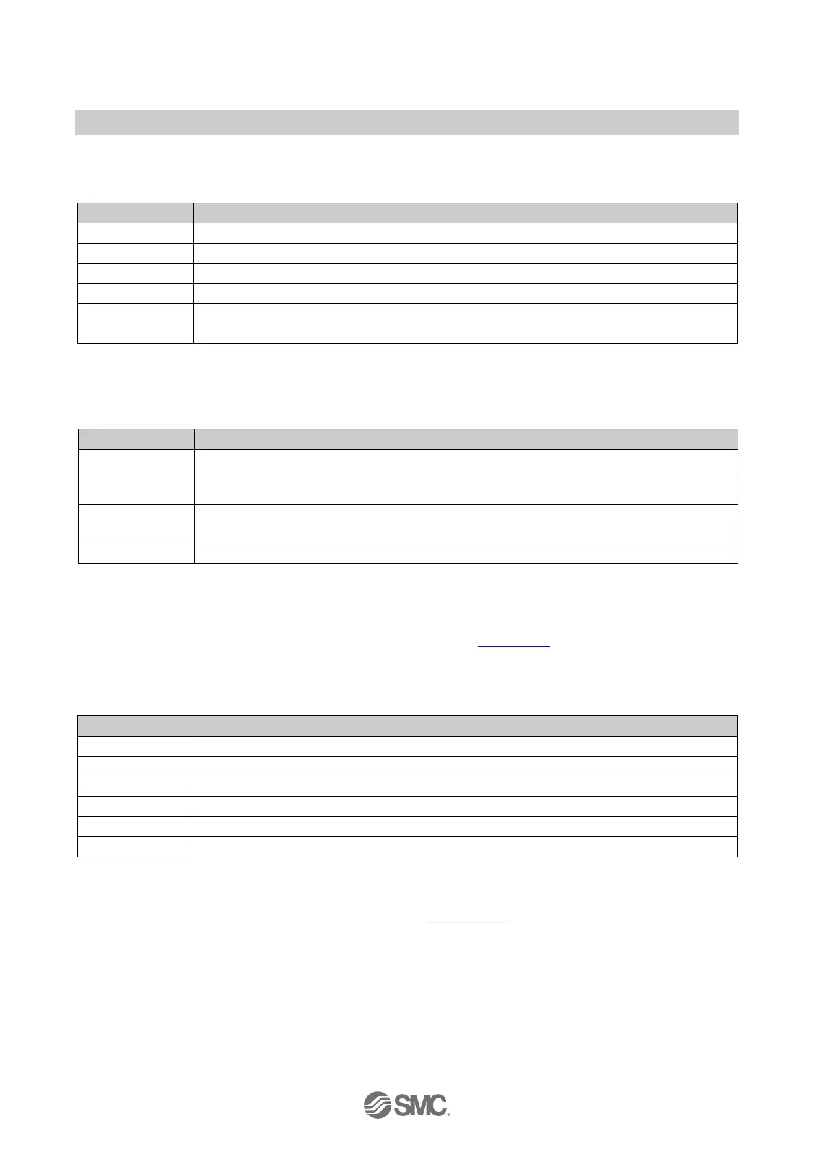
6.4.4. LINK/ACT indicator
Table. 6-6 LINK/ACT indicator
Connection via Ethernet to the SI Unit via Port 1/2 (XF1/XF2)
Green OFF No connection established via Port 1/2 (XF1/XF2)
Transmission or reception of Ethernet telegrams on Port 1/2 (XF1/XF2)
No transmission or reception of Ethernet telegrams on Port 1/2 (XF1/XF2)
Flash
∗
at 1 Hz
Received node flash request
∗: The LINK (green) and ACK (orange) LEDs flash same time
6.4.5. FO indicator
Table. 6-7 FO indicator
OFF
No fault.
The strength margin of the Fibre-optic communication is more than 2 dB on Port 1/2
(XF1/XF2).
Flash
at 1 Hz
The strength margin of the Fibre-optic communication is more than 0 dB but less than
2 dB on Port 1/2 (XF1/XF2).
The strength margin of the Fibre-optic communication is 0 dB on Port 1/2 (XF1/XF2).
NOTE
・ If monitor setting of communication port is enable, the FO indicator shows the status of the
maintenance alarm for the Fibre-optic cables, refer to Section 5.2
.
6.4.6. LED indicator during energy saving mode for PROFIenergy
Table. 6-8 LED indicator during energy saving mode for PROFIenergy
NOTE
・ For module parameter of PROFIenergy, refer to Section 4.2.2.
 Loading...