- 82 -
No.EX※※-OMW0011-B
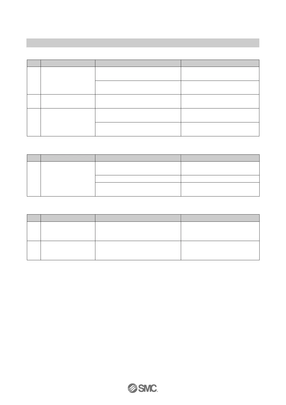
Table. 13-4 Troubleshooting for the problem with display on US1/US2 LED
1 US1 indicator is OFF.
Incorrect wiring.
Check the cable.
Check the wiring and pin numbers.
US1 is not present.
Check the supply for US1
(sensor/input) of the SI Unit.
2
US1 indicator is
flashing.
US1 is below the permissible level (<
approx. 19.2 VDC).
Check the supply for US1
(sensor/input) of the SI Unit.
3 US2 indicator is OFF.
Incorrect wiring.
Check the cable.
Check the wiring and pin numbers.
US2 is not present.
Check the supply for the
valves/loads.
Table. 13-5 Troubleshooting for malfunction of the solenoid valve
1
A solenoid valve is not
operating.
Incorrect mounting of valve manifold.
Check the mounting of the SI Unit
and valve manifold.
Solenoid valve is faulty.
Check the solenoid valve.
US2 is not present.
Check the supply for the valves.
Check the wiring and pin numbers.
Table. 13-6 Troubleshooting for the problem with display on FO LED
1
FO1 or FO2 indicator is
flashing.
The strength margin of the Fibre-optic
communication is more than 0 dB but
less than 2 dB on Port 1/2 (XF1/XF2).
Check the Fibre-optic cable.
2
FO1 or FO2 indicator is
ON.
The strength margin of the Fibre-optic
communication is 0 dB on Port 1/2
(XF1/XF2).
Check the Fibre-optic cable.
 Loading...