- 21 -
No.EX※※-OMW0011-B
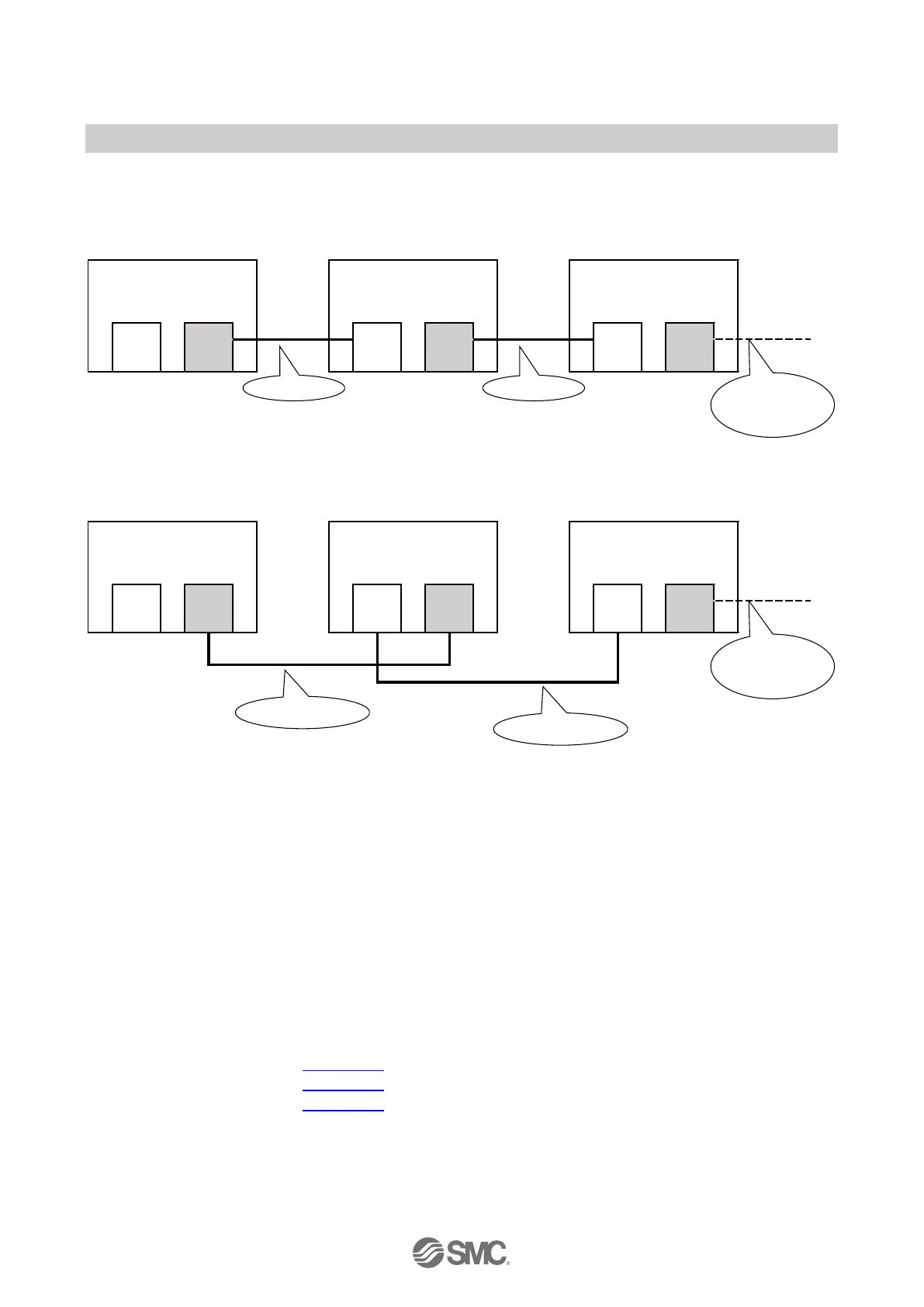
Connection example
Case 1
EX245-SPN2A/SPN3A
- Priorized startup (FSU)
- Disable Autonegotiation
IO controller or Switch
- Disable Autonegotiation
EX245-SPN2A/SPN3A
- Priorized startup (FSU)
- Disable Autonegotiation
Cable type
dependent upon
next port settings
Case 2
IO controller or Switch
- Disable Autonegotiation
EX245-SPN2A/SPN3A
- Priorized startup (FSU)
- Disable Autonegotiation
EX245-SPN2A/SPN3A
- Priorized startup (FSU)
- Disable Autonegotiation
Cable type
dependent upon
next port settings
Fig. 3-12 Connection examples when using Disable Autonegotiation
3.2.2. FE terminal
The SI Unit must be connected to FE (Functional Earth) to divert electromagnetic interference. The
FE terminal and the FE pin of the two power connectors (XD1/XD2) are internally connected. Please
connect at least one of these three FEs to ground potential. For maximum protection the FE cable
should be as thick and short as reasonably possible. If it is difficult to shorten the power cable, it is
recommended to use the FE terminal screw.
3.2.3. Sensor/Load/IO-Link device connection
Regarding the wiring of each module, refer to following section:
・ EX245-DX1 : Section 7.3
・ EX245-DY1 : Section 8.3
・ EX245-LA1 / LB1 : Section 9.3
 Loading...