HRX-OM-M090
Chapter 2 Name and Function of Parts
2.4 Operation display panel HRS Series
2-4
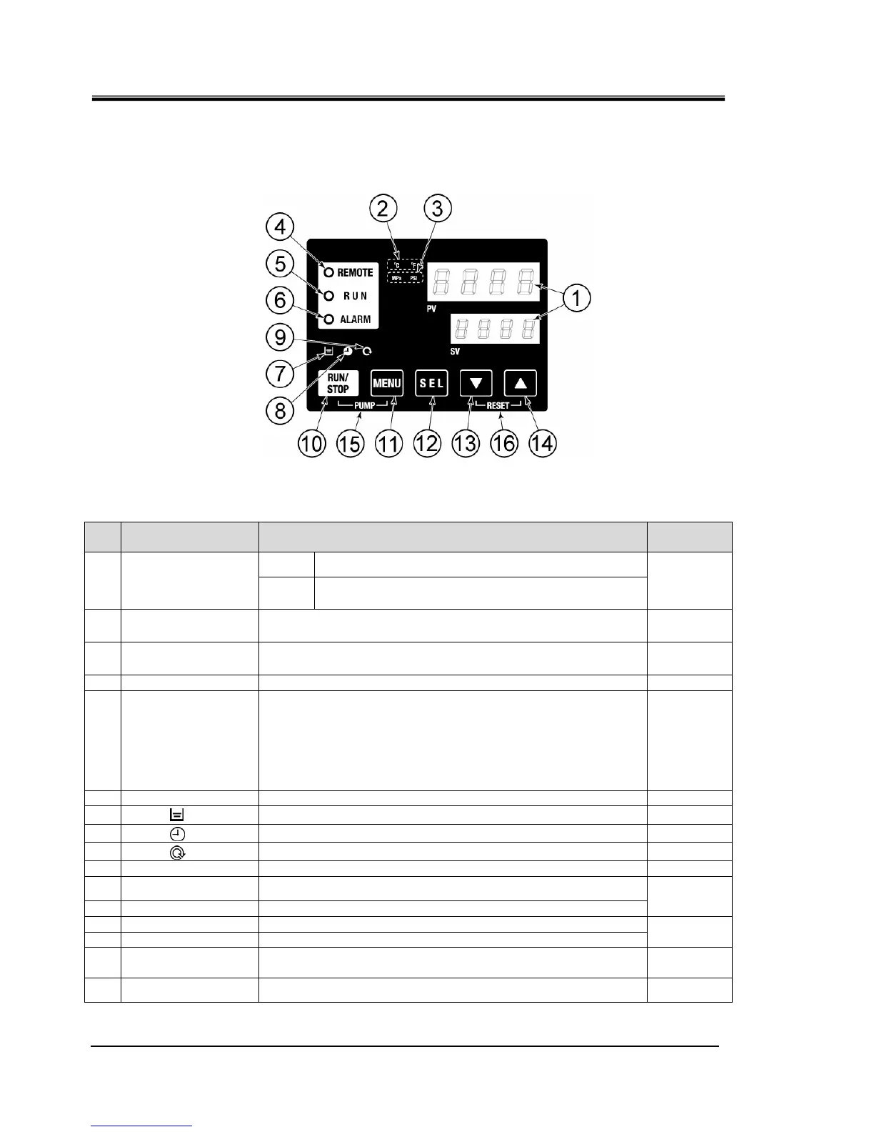
2.4 Operation display panel
The operation panel on the front of the product controls the basic operation
of the product.
Fig. 2-3 Operation display panel
Table 2-3 Operation display panel
No Description Function
Reference
page
PV
Displays the temperature and pressure of the circulating
fluid and alarm codes.
①
Digital display
(7 segment,
4 digits)
SV
Displays the set temperature of the circulating fluid and
the set values of other menus.
5.2
② [
o
C
o
F ] lamp Displays the unit of display temperature (℃ or
o
F). 5.12
③ [MPa PSI] lamp Displays the unit of display pressure (MPa or PSI). 5.13
④ [REMOTE] lamp Lights up during remote operation by communication. 5.18
⑤ [RUN] lamp
・Lights up when the product is started and in operation. Goes off
when the product is stopped.
・Flashes during stand-by for stop (Interval 0.5 seconds).
・Flashes during independent operation of the pump (Interval
0.3 seconds).
・Flashes during anti-freezing function (At standby: Interval 2
seconds, At operation: Interval 0.3 seconds).
4.4
⑥ [ALARM] lamp Flashes with buzzer when alarm occurs (Interval 0.3 seconds). 5.3
⑦
[ ] lamp Lights up when the tank level indicator falls below the LOW level. 4.3
⑧
[ ] lamp Lights up while the run timer or stop timer function is working. 5.6
⑨
[ ] lamp
Lights up when the product is in automatic operation.
5.9
⑩ [RUN/STOP] key
Makes the product start or stop.
4.4
⑪ [MENU] key
Shifts the main menu (display screen of temperature) the other
menu (entry of set values and monitor screen).
⑫ [SEL] key
Changes the item in menu and enters the set value.
5.1
⑬ [▼] key
Decreases the set value.
⑭ [▲] key
Increases the set value.
-
⑮ [PUMP] key
When the [MENU] and [RUN/STOP] keys are held down
simultaneously, the pump starts running independently.
4.3
⑯ [RESET] key
Keep the [▼] and [▲] keys pressed down simultaneously. This will
stop the alarm buzzer and reset the [ALARM] lamp.
6.3
 Loading...


