HRX-OM-M090
Chapter 3 Transport and Setting Up
3.7 Wiring of external switch HRS Series
3-20
3.7 Wiring of external switch
This product can be monitored by sampling the signal of the external switch
prepared by the customer.
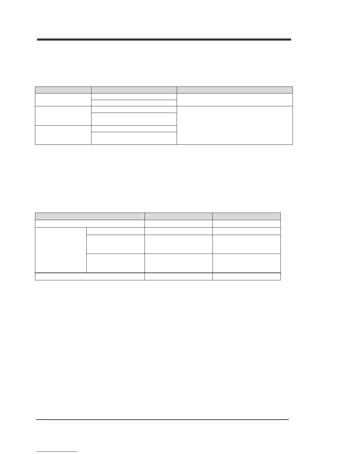
Table 3-6 Power supply, contact specifications
Name Terminal NO. Specification
12(DC 24V)
Power supply output
11(24V COM)
DC 24V ±10% 0.5A MAX
∗
1
10(Contact input signal 1)
Contact input signal
1
9(Common of contact output
signal 1)
8(Contact input signal 2)
Contact input signal
2
7(Common of contact output
signal 2)
NPN open collector output
PNP open collector output
*1:To use the power of the device, the total load current must be 500mA or less.
If the load is 500mA or more, the internal fuse will be cut to protect the product and the alarm [AL21 DC
line fuse cut] will be generated. Refer to Chapter 6 for handling of alarms.
One external switch can be connected to contact input signal 1 and one to
contact input signal 2. (Two in total) The external switch cannot be
connected to the contact input signal 1 depending on the communication
mode. Table 3-7 shows the setting.
Table 3-7 Sets external switch
Communication mode ∗1
Contact input signal 1 Contact input signal 2
Local mode
○ ○
MODBUS
○ ○
Simple
communication
protocol 1
○ ○
SERIAL mode
Simple
communication
protocol 2
× ○
DIO mode
× ○
*1:Refer to the Communications Operation Manual for more details of each mode.
Local mode: Mode allowing the product to be operated by the operation panel. (Default setting)
SERIAL mode: Mode allowing the product to be operated by serial communication.
DIO mode: Mode allowing the product to be operated by the contact input/output communication.
 Loading...


