HRX-OM-M090
Chapter 3 Transport and Setting Up
HRS Series 3.3 Installation
3-11
3.3.4 Wiring of remote operation signal input
The remote signal input is to enable the product to be run and stopped
remotely by applying a contact signal input. This chapter illustrates
examples of wiring
Select DIO mode as the communication mode to activate the remote control
signal input. After wiring, select DIO mode referring to the Communications
Operation manual.
【Tips】
This product has two input signals. These can be customized depending on
the customer’s application.
Refer to the Operation Manual for communication for details.
1. For operation using remote signal, prepare the switch (source voltage: 24V, contact
capacity: 35mA or more, min. load current: 5mA), and cable (dia. 0.14 to 1.5mm2).
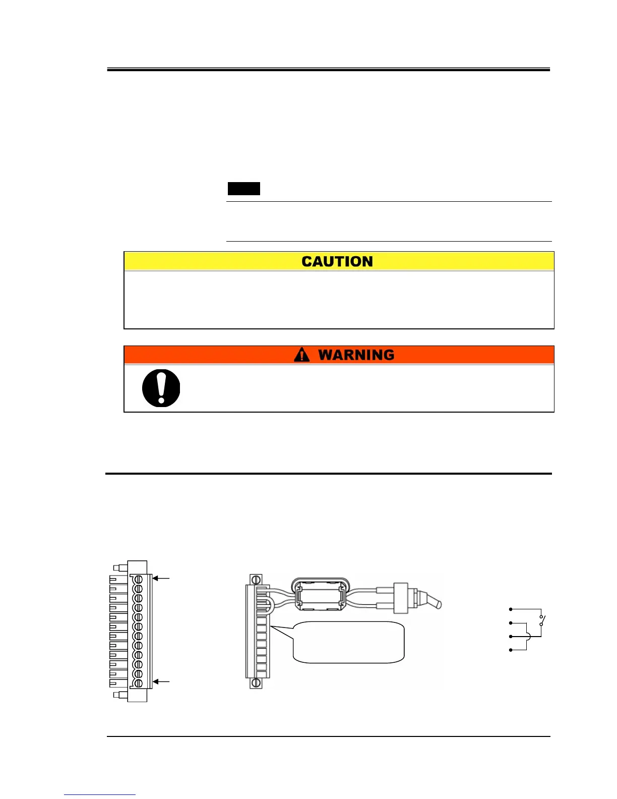
2. Connect the remote control cable and the switch to the connector for the contact
input/output, supplied as an accessory. Then, mount the ferrite core (3 turn) supplied as
an accessory. (See below) (This is an example of wiring. Refer to the Operation Manual
for communication for details.)
Fig. 3-7 Wiring of contact for remote signal inputs(Example)
Terminal no.1
Terminal no.12
Switch
Recommended
accessory cable dia. is
0.14 to 1.5mm
2
9
〃
12
11
10
Terminal no.
〃
〃
The capacity of the output contact of the product is limited. If the capacity is not
large enough, install a relay, etc. (to allow for larger capacity). At the same time,
ensure the input current of the relay is small enough in relation to the contact
capacity of the product.
Be sure to shut off the breaker of the facility power supply (the user’s
machine power supply) before wiring.
 Loading...


