!+).3/)'1+6:/7+2+398
'-+ ? +)9/437+5'7'9/43 389'11'9/43'3:'1
%#$ #$
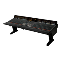
The console surface, Alpha-Link I/O units and the MORSE racks do not contain cooling fans so can be located in recording
areas provided that there is sufficient air conditioning capacity.
The Blackrock processor is fitted with cooling fans and is expected to be housed in a separate ‘Machine’ room. Adequate
noise isolation should exist between the machine room and the Control Room/recording areas.
The RIO I/O chassis is fitted with temperature controlled lower-noise fans so will also requires a degree of noise isolation
from recording areas.
Noise figures for the individual units are listed in the Specifications section from page 4-2.
" $ "!%"$#
Air conditioning will almost certainly be required for both the equipment and control rooms in order to maintain the
temperature and humidity to the required levels.
Note that a RIO unit fitted with multiple microphone channels can generate significant heat output so must always be
operated in a cooled environment.
Power dissipation and environmental requirement figures are listed in Appendices A and E.
%$
Cable ducting will be required between the console and the equipment room (as well as to any outboard racks and the
recording areas). The ducting provided should be of sufficient size such that approximately 50mm x 35mm is available for
console surface connection. This should be sufficient for the analogue and digital cabling for metering and the T/B Mic etc.
in addition to the console network connections.
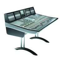
The connectors for all control and interface cables are located beneath the console’s centre section. The connector panels
are orientated so that cables will exit downwards at the rear of the desk. It is not possible to route cables through the
console legs.
The console mains input connectors are located beneath the bay to the left of the centre section.
#"& ##
Access to all electronic assemblies within the frame is from either the front or above the console. The power supplies are
located in the knee panel area. There are PCB assemblies located behind the channel TFT meter screens. To remove a
TFT screen it will be necessary to remove the top trim. This trim is secured using screws along the rear of the top edge.
If the console is being built into restricted space – as in some mobile installations – then allow sufficient clearance above
the top trim for access to the fixing screws.
Clearance for service access will also be required in front of and behind the rack into which the Blackrock processor and
RIO units are installed so that cards can easily be removed. See the drawing on pages 2-10 and 2-14 for minimum
clearances.
 Loading...
