# $"#
! "! XLR-3 male
The centre control tile of the console is fitted with a talkback microphone. The output signal is analogue, balanced and at
approximately 0dBu. Page 3-23.
#"
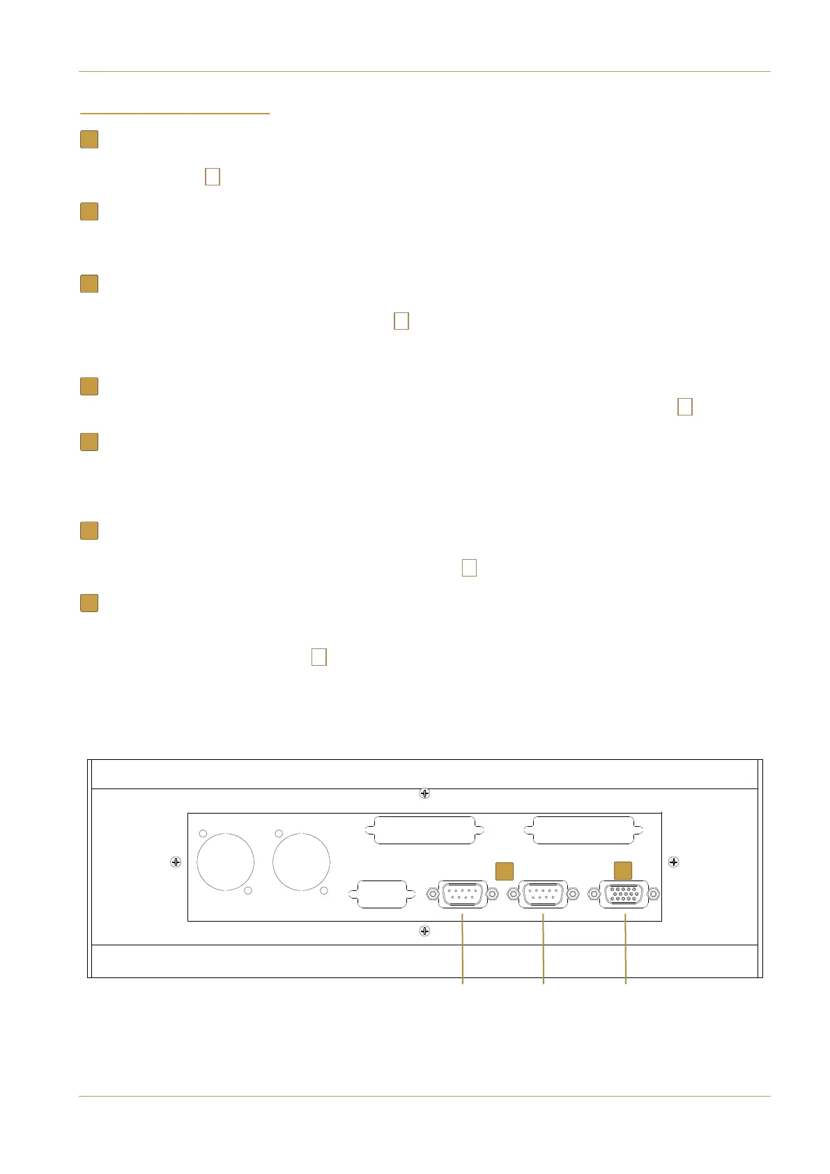
! " " D25 male
VU meter inputs. If a phasescope with analogue inputs has been specified then this connector will also supply the meter’s
analogue inputs.
! D25 female* ! D9 female*
Phasescope digital inputs. Pinout will depend on which model of phasescope is chosen. For both the RTW and DK meters
a D9 diagnostic/terminal connector will also be fitted. Page 3-23.
*Both connectors are only fitted if a phasescope has been specified.
!$ ! RJ45
These connectors link the console to its Blackrock processor(s). Standard Ethernet cables can be used. Page 3-5.
!
" &" USB
For the connection of an external USB keyboard as a method of text entry as an alternative to the touchscreen. An infra-
red wireless combined keyboard/trackball is included as standard. The keyboard’s IR receiver will need to be located above
the console’s top trim.
!
" #"!"! HD15F
Mirrored video output of the centre section touchscreen. Can be connected to an external XGA monitor for backup or
training purposes (note that the display is in portrait orientation). Page 3-27.
! D9 male
Two 9-pin serial ports are available for the connection of 3rd party equipment to provide router naming and automation
control. Automatic control backup will be included on systems that are equipped with processor redundancy. Allocation
of function is setup in system software. Page 3-27.
1
2
3
4
5
6
7
>89+242543+398
389'11'9/43'3:'1 +)9/437+5'7'9/43? '-+
$ $"
# 5 x blank for user option
Touchscreen
VGA Out
RS422
Serial 1
RS422
Serial 2
#
#
# #
#
6
7