##)#$ $#
##
" )%$
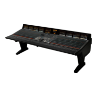
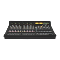
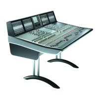
Each console control surface will consist of a centre section and from 16 to 64 channel faders in groups of 8. (A group of
8 faders, controls and frame is often termed a ‘).'33+1('>’).
The number of physical faders fitted to a console surface does not limit the number of processing channels available; this is
determined solely by the quantity of DSP resource fitted to the Blackrock processor. DSP processing is available in blocks of
32 between 64 channels and 256 channels.
! !
Each console channel bay comprises four separate panels (referred to as ‘9/1+8’): faders, channel-control, master-channel
and the TFT meters. A master-channel tile provides physical access to all operational controls for a channel strip and can
be assigned to control any of the channels in the entire console. Because of this flexibility master-channel tiles do not need
to be fitted to every bay in the frame; although, for convenience and operator flexibility, master tiles can be fitted to any
bay. It is recommended that at least one master-channel is fitted to each side of the centre section
!
The centre section is fitted with two analogue mechanical VU meters.
Space is available into which an LCD phase-scope can be fitted. Two types available to order: RTW Touchmonitor TM-7
(8ch analogue plus 8ch digital) or the MSD600M (8ch digital as standard but modular and customisable). Both phase-scopes
feature loudness metering as standard.
!
The console frame is supplied with flat sides as standard to reduce the overall width. Contoured side arms are available
but need to be specified as an option. These will add 72mm to the overall console width.
$" #
The I/O connector panel (see diagram opposite) is located beneath the centre section of the console. The mains input
panel is located beneath the bay to the left of the centre section.
The mounting pillars for the D-sub connectors fitted to the connector panel use the UNC-440 thread.
>89+242543+398
389'11'9/43'3:'1 +)9/437+5'7'9/43? '-+
>89+242543+398
 Loading...
