&"
The Alpha-Link LIVE-R is a 2U high 300mm deep 19” rack unit featuring dual power supplies for on-air reliability.
Output levels at 0dBfs are user adjustable to cover the range +14dBu to +24dBu.*
Each Alpha-Link Live-R provides 24 channels of line-level analogue input & output and also 24 channels of AES/EBU input
& output. Digital channels 1–8 feature sample rate conversion on their inputs; circuits 9–24 operate at the system sample
rate.
The line outputs from the 8-RMP remote Mic amps are connected to the Alpha-Link Live analogue input sockets. When
allocating audio circuits ensure that a sufficient number of analogue inputs are reserved for any Mic channels.
" $
Alpha-link Live units are connected to the Blackrock processor using fibre optic cabling. Suitable cables should be installed
by the facility. Fibre specification is: 50/125µm multimode duplex LC to SC.
The unit will, by default, select the MADI-1 input connector. Should the MADI-1 signal become lost – as a result of a
broken or disconnected fibre – the unit will automatically switch to its MADI-2 input.
$" #%")
*Alpha-Link LIVE-R only, see below.
See Section 4-11 for the connector pinouts.
&
Alpha-Link Live is operationally the same as the ‘LIVE-R except in the following areas:
• Only a single MADI fibre connector is included. See panel layout opposite.
• Two versions of the unit are available which provide either +18dBu or +24dBu analogue output level at 0dBfs. This
setting is NOT user-selectable so the version required must be specified at the time of order.
• The ‘RMP 1, 2 & 3’ control connectors have a different pinout. Standard Ethernet cables CANNOT be used.
Refer to Appendix page 4-12.
• The USB connector is not fitted. The additional ‘Expansion Port’ connector is not used and does not require a
connection.
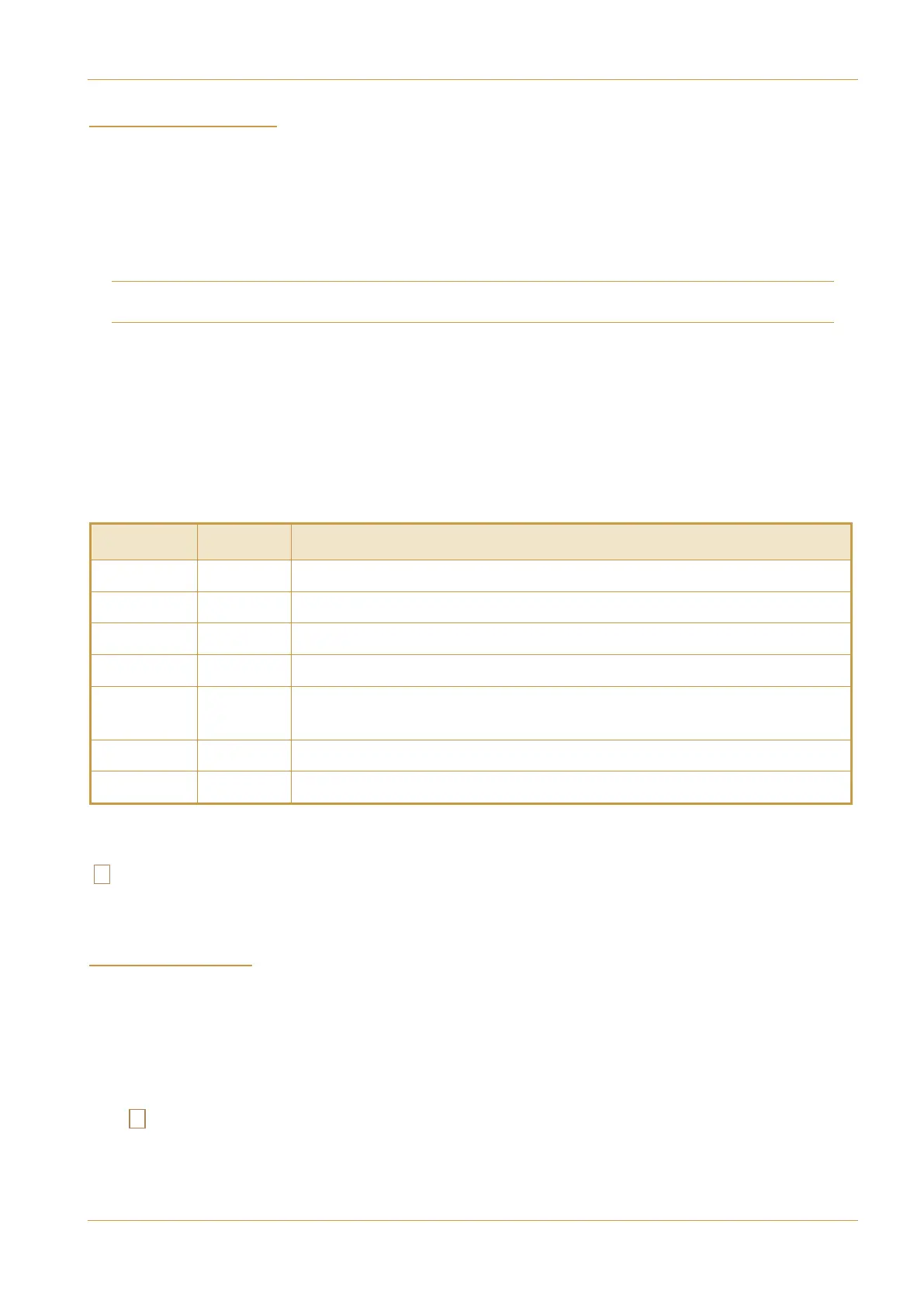
'2+ 433+)947 +8)7/59/43
Analogue D25 F 8 channels, balanced, line-level audio input or output per connector.
AES/EBU D25 F 4 AES/EBU input pairs plus 4 AES/EBU output pairs per connector.
MADI SC Fibre MADI audio data link to the console DSP processor.
Remote 1,2,3 RJ45 Control link to the 8-RMP remote mic units. Standard Ethernet cables can be used.*
Video In
75Ω BNC
Video sync input required. (Alternatively, sync can derived from the incoming MADI stream
but with slightly reduced technical performance.)
Wclock Out
75Ω BNC
Provides a source of Wordclock output locked to console sync input.
USB USB-B No connection required. Service diagnostic use only.*
>89+242543+398
389'11'9/43'3:'1 +)9/437+5'7'9/43? '-+