"D "
The microphone input card provides 12 input channels accessible via standard XLR 3-pin female connectors.
The card has been specifically designed to operate in a broadcast environment and meets recognised performance
standards. The card is fitted with RF input filtering, a high-speed analogue limiter and features high input CMRR.
Switchable phantom power is available.
"D% "
The analogue card provides 24 channels of balanced line-level input and output. At least one analogue card will need to
be included if analogue monitor amplifiers are being used. The connectors used for input and output are Canon DL96
types. Mating connector kits and a contact crimp tool can be supplied (as cost options).
Connector pinouts are listed on page 4-10.
"D$ "
The digital I/O card is available in two versions: 110Ω and 75Ω. Both types provide 64 channels – 32 AES/EBU pairs – of
digital input and output. The 110Ω card provides balanced output signals whereas the 75Ω card is unbalanced for correct
matching to coaxial cables. Sample rate conversion is available on every input so the card can accept input rates from
32kHz to 96kHz. The connectors are all D-25 type females and mating connector kits are available (as a cost option).
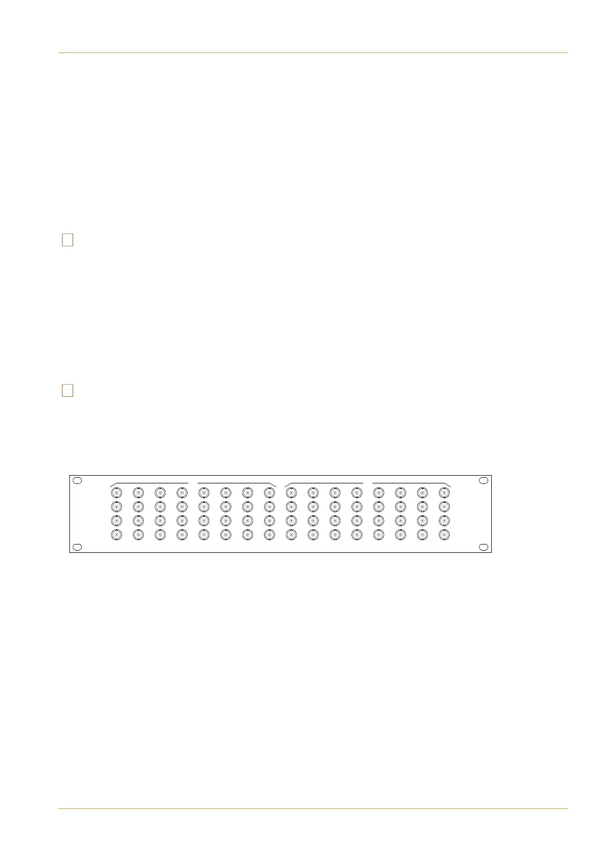
A breakout panel is available for the 75Ω card. This panel converts the I/O card’s D-25 connectors to chassis BNC plugs
and can be ordered with 1m or 3m interconnecting leads. Do not attempt to extend the panel interface leads beyond the
3m maximum as doing so could increase the risk of data corruption.
Connector pinouts are listed on page 4-10.
Ω
"!
>89+242543+398
389'11'9/43'3:'1 +)9/437+5'7'9/43? '-+
1
3
5
7
2
4
6
8
9
11
13
15
10
12
14
16
17
19
21
23
18
20
22
24
25
27
29
31
26
28
30
32
IN
1
3
5
7
2
4
6
8
9
11
13
15
10
12
14
16
17
19
21
23
18
20
22
24
25
27
29
31
26
28
30
32
OUT