#$$
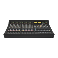
C100 HDS systems are supplied with mains leads, sync termination and short cables to allow the system to be connected
for initial testing. Systems are not supplied with the longer runs of network, fibre, sync or other cabling necessary to
connect remote I/O boxes or to integrate with associated studio systems. The cables which form part of the studio
infrastructure will need to be sourced and installed by the facility or systems integrator.
$'" #
Standard RJ45 Cat-5e or Cat-6 Ethernet cables can be used. The maximum permissable length of any cable run is 100m.
Cables will need to be installed between the console surface and the equipment area housing the Blackrock processor(s) –
two separate cables should be installed to provide a redundant connection. Additional cabling will be required between
the Blackrock and its I/O units and also the Blackrock and the file management PC.
Pee pages 2-8 and 3-4 for additional network cabling information.
#) #
Sync must be distributed using 75Ω coaxial cable terminated with 75Ω BNC connectors.
The sync signals provided must be from a common source to all equipment. For example, if both video and Wordclock
signals are being used then Wordclock must be generated by, or locked to, the video sync generator.
% #
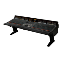
The console surface includes an inbuilt talkback microphone with amplifier and the centre section meter panel is fitted
with two mechanical VU meters as standard. To use these features audio wiring will need to be installed between the
console surface and the I/O units and/or the facility’s comms system.
Additional circuits will need to be installed between the console and analogue I/O if a phasemeter with analogue inputs
has been specified.
$ #
Digital wiring will need to be installed if a phasemeter with digital inputs has been specified. Both meter types available
include 8 (4 AES/EBU pair) digital input channels.
Cables used for AES inputs should be 110R balanced.
#" #
C100 systems include the ability to communicate with routers and automation systems. RS422 serial cables will need to
be installed between the console surface, or the Blackrock processor and the remote devices.
Two serial ports are fitted to the console surface and a single port is fitted to the Black rear panel. Note that only two
ports can be in use at the same time.
.>8/)'1+6:/7+2+398
389'11'9/43'3:'1 +)9/437+5'7'9/43? '-+
 Loading...
