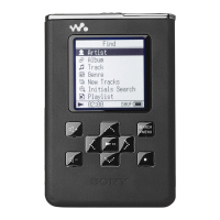
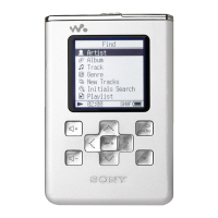
HAP-S1
103
Pin No. Pin Name I/O Description
62 AVSS - Ground terminal
63 PWR LED GRN O LED drive signal output terminal for the power indicator “H”: LED on
64 NC - Not used
65 SIRCS IN I SIRCS signal input from the remote control receiver
66 PLAY KEY I Play key input terminal (A/D input)
67 POWER KEY I Power key input terminal (A/D input)
68 MODEL I Model setting terminal Fixed at “L” in this unit
69 DST I Destination setting terminal Fixed at “L”
70 A_LEVEL_DET I Speaker level detection signal input terminal
71 PROG SCK O Program clock signal output terminal
72 PROG SYS/JIG O Program data output to the MPU
73 PROG JIG/SYS I Program data input from the MPU
74 NC - Not used
75 VSS - Ground terminal
76 VCC - Power supply terminal (+3.3V)
77 NC - Not used
78 TCK I Clock signal input terminal for the JTAG
79 TMS O Mode selection signal output terminal for the JTAG
80 TDO O Data output terminal for the JTAG
81 TDI I Data input terminal for the JTAG
82 to 84 NC - Not used
85 AMP_TEMP1 I Temperature sensor input terminal
86, 87 TEST1, TEST2 - Not used
88 STBY_EN O Power cut on/off control signal output terminal for the sub power “H”: sub power cut on
89 FAN_EN O Fan motor on/off control signal output terminal “H”: fan motor on
90 FAN_SLOW/FAST O Fan motor speed selection signal output terminal “L”: slow, “H”: fast
91 TEST3 - Not used
92 LINE_RY O Line muting on/off control signal output terminal “L”: muting on
93 NC - Not used
94 E2P SCL O Serial data transfer clock signal output to the EEPROM
95 E2P SDA I/O Two-way data bus the EEPROM
96 A_SEL1 O Analog audio selection signal output terminal “L”: D/A converter audio, “H”: LINE IN audio
97 VCC - Power supply terminal (+3.3V)
98 A_SEL2 O Analog audio selection signal output terminal “L”:LINE IN 1 audio, “H”: LINE IN 2 audio
99 NC - Not used
100 VSS - Ground terminal

 Loading...


