27
HCD-FL3
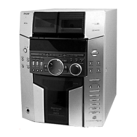
4. Mode: Record
5. Mode: Playback
6. Confirm the play back signal recorded in step 3 becomes
adjustable level as follows.
If these levels are not adjustable level, adjust the RV53 (R-CH)
on the SP RELAY board to repeat steps 4 and 5.
Adjustable level:
CN804 PB level: 47.2 to 53.0 mV (–24.3 to –23.3 dB)
Adjustment Location: SP RELAY board
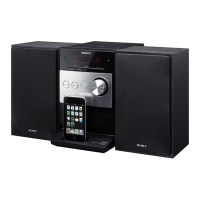
REC BIAS ADJUSTMENT DECK B
Procedure:
In the MC test mode, the “REC memory mode” is convenient for
this adjustment. In the “REC memory mode” , when the REC starts
the input signal FUNCTION is switched to VIDEO automatically.
When the REC stops, the tape returns near to the recording start
position.
1. Press [MD $VIDEO%] button to select VIDEO. (This step is not
necessary if the above test mode has already been set)
2. Insert a tape into deck B.
3. After press [REC PAUSE/START] button, press [REC PAUSE/
START] button, then recording start.
4. Mode: Record
5. Mode: Playback
6. Confirm the playback signal recorded in step 3 becomes
adjustable level as follows.
If these levels are not adjustable level, adjust the RV2 (L-CH)
and RV52 (R-CH) on the SP RELAY board to repeat steps 4
and 5.
Adjustable level: Playback output of 315 Hz to playback output
of 10 kHz: ±1.0 dB
Adjustment Location: SP RELAY board
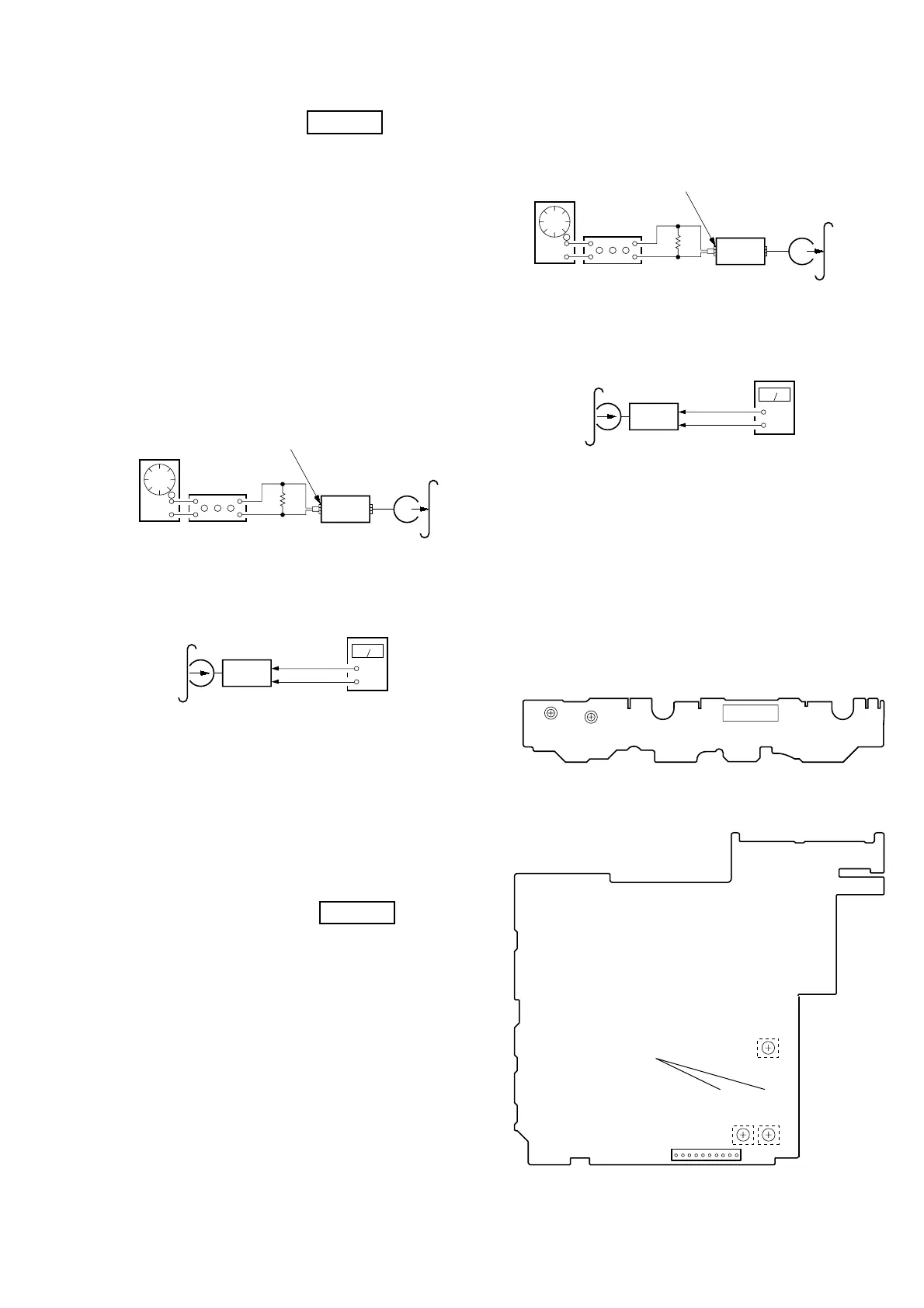
REC LEVEL ADJUSTMENT DECK B
Procedure:
In the MC test mode, the “REC memory mode” is convenient for
this adjustment. In the “REC memory mode” , when the REC starts
the input signal FUNCTION is switched to VIDEO automatically.
When the REC stops, the tape returns near to the recording start
position.
1. Press [MD $VIDEO%] button to select VIDEO. (This step is not
necessary if the above test mode has already been set)
2. Insert a tape into deck B.
3. After press [REC PAUSE/START] button, press [REC PAUSE/
START] button, then recording start.
attenuator
set
DSP board
MD (AUDIO) (J701)
1) 315 Hz
2) 10 kHz
50 mV (–23.8 dB)
600
Ω
blank tape
CN-123
AF OSC
+
–
set
recorded
portion
SP RELAY board
CN804 Pin
3
(GND)
SP RELAY board
CN804
Pin
2
(L-CH)
Pin
5
(R-CH)
level meter
set
DSP board
MD (VIDEO) (J701)
315 Hz, 50 mV (–23.8 dB)
blank tape
CS-123
600
Ω
attenuator
AF OSC
+
–
set
recorded
portion
SP RELAY board
CN804 Pin
3
(GND)
SP RELAY board
CN804
Pin
5
(R-CH)
level meter
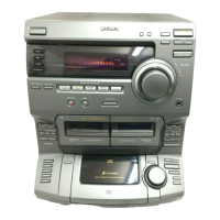
TAPE SPEED
ADJUSTMENT
RV1002
RV1001
(NORMAL) (HIGH)
CN1001
– SW BOARD (Component Side) –
CN804
10
1
– SP RELAY BOARD (Conductor Side) –
REC BIAS
ADJUSTMENT
REC LEVEL
ADJUSTMENT
(L-CH)
(R-CH)
RV52
RV2
RV53