45
Signal Selection
Chapter 3 Signal Selection and Transitions
Signal Selection
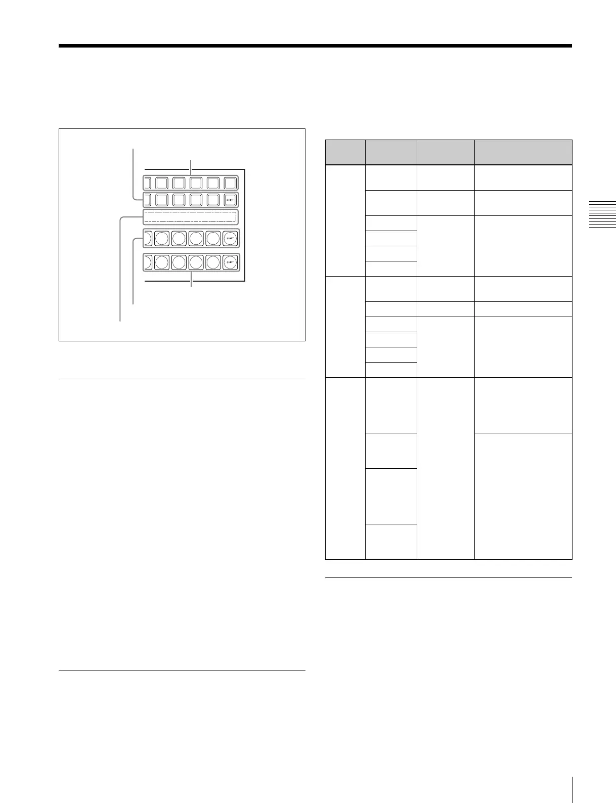
You carry out signal selection in the cross-point control
block of each bank.
Cross-point control block
Basics of Signal Selection
Each of the switcher banks have 24 cross-point buttons in
their cross-point control blocks.
These buttons are identified by numbers common to all of
the banks and blocks, and a signal is assigned to each
number.
The basis of signal selection is to select, in a cross-point
button row, the cross-point button to which the desired
signal is assigned.
M/E reentry signal selection
A video signal created on the M/E bank can be imported as
an input signal on the PGM/PST bank. These signals are
referred to as “M/E reentry input” signals.
To select an M/E reentry input signal using the cross-point
buttons, the signal must be assigned beforehand in the
Setup menu (1 p. 223).
For example, if the program output from the M/E-1 block
(M/E1 OUT) is assigned to an arbitrary cross-point button,
the signal can be used as input material at any time.
Bus Selection
Each row of the 24 cross-point buttons is shared by
multiple buses.
The following table illustrates the correspondence
between buses and cross-point button rows, and the
delegation operations.
Signal Assignment and Selection
Assigning signals to buttons
Each of the 24 cross-point buttons has a corresponding
button number, to which you assign a signal.
In addition to the signals input to the connectors at the rear
of the switcher processor, you can also select signals
generated within the switcher.
Each button has assigned to it a video signal and a key
signal, forming a pair. You can set these video and key
combinations in the Setup menu.
Source name display
Background B row
Background A row
2nd row
1st row
Bank Bus name Cross-point
button row
Delegation operation
M/E-1
Background
A bus
Background
A row
–
Background
B bus
Background
B row
–
Key 1 bus 2nd row In the 1st row, press
the button to which the
corresponding key
was assigned during
setup, turning it on.
Key 2 bus
Key 3 bus
Key 4 bus
PGM/
PST
Program
bus
Program
row
–
Preset bus Preset row –
DSK 1 bus 2nd row In the 1st row, press
the button to which the
corresponding key
was assigned during
setup, turning it on.
DSK 2 bus
DSK 3 bus
DSK 4 bus
M/E-1
PGM/
PST
Utility bus 2nd row In the 1st row, press
the button to which
UTIL1 was assigned
during setup, turning it
on.
AUX1 to
AUX24
buses
In the 1st row, press
the button to which the
corresponding bus
was assigned during
setup, turning it on.
Frame
memory
source 1
and 2
buses
Edit
preview
bus