51
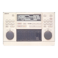
Locations and Functions of Parts
f Display window
1 REF IN/OUT indicators
Display whether to use the REF IN/OUT connectors as an
input connector or an output connector. The REF IN/OUT
can be set using the setup menu item 17 (see page 76).
The REF indicator also shows the following condition:
The REF indicator lights up: When a reference signal
that matches the setting of this unit is input.
The REF indicator flashes: When no reference signal or
the reference signal of different system frequency is
input in editor mode.
The REF indicator turns off: When no reference signal
or the reference signal of different system frequency is
input in remote control mode.
When the system frequency is set to 29.97 or 25 frames,
the REF IN/OUT connector cannot be used as an output
connector.
2 System frequency indicators
Display the system frequency. The system frequency can
be set using the setup menu item 15 (see page 76).
3 IN/OUT (Edit start point/edit end point) indicators
Light up when the IN/OUT points are entered.
When the IN and OUT indicators flash simultaneously
You cannot perform the automatic editing because the
OUT point is entered before the IN point.
4 ALARM indicator
Lights up when an error occurs. Simultaneously, an error
message is displayed.
5 LEARN indicator
Lights up while this unit is detecting the start delay time of
the connected VTR.
6 REC indicators
Lights up when the VTR or device connected to this unit is
recording.
7 RTC/TC/CTL indicators
Displays the type of the time data set with the TC/RTC/
CTL button.
8 SERVO indicators
Light up when the servo-mechanism of the VTR is locked.
9 Time data display
Displays the time data, setup menu, or error messages.
When the tape recorded in drop frame mode is played back
or edited, the drop frame mode indicator lights up.
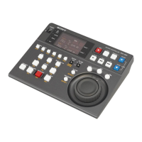
2 Running Control Area
Note
IN OUT
PLAYER
RTCTL
DEVICE 2
RECORDER
RTCTL
DEVICE 1
2 System frequency
indicators
4 ALARM indicator
3 IN/OUT indicators
8 SERVO indicators
1 REF IN/OUT indicators
5 LEARN indicator
7 RTC/TC/CTL indicators
6 REC indicators
9 Time data display
Drop frame mode indicator
JOG
SHTL
PLAYER
DEVICE 2
DEVICE 1
RECORDER
REC EDIT PREROLL PAUSE
PLAY REW FF STOP
STANDBY
RM
-
280
EDITING CONTROLLER
VAR
2 EDIT button
3 PREROLL button
1 VTR operation buttons
4 STANDBY indicator
5 PLAYER (DEVICE 2)/
RECORDER (DEVICE 1)
buttons
6 Search dial and indicators
7 SHTL/JOG/VAR buttons