53
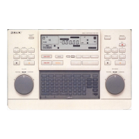
Locations and Functions of Parts
b ASSEMBLE (assemble editing) button
Press to select assemble editing mode. The button lights
up.
Press again to cancel the assemble editing mode.
c TRIM +/TRIM – buttons
Press the TRIM + or TRIM – button simultaneously with
the IN or OUT button to modify the edit point by frame.
Press the TRIM + button to advance one frame. Press the
TRIM – button to go back one frame.
d INSERT (insert editing) buttons
The INSERT buttons consist of the VIDEO button and
four audio channel buttons.
Press the desired button or buttons select the insert editing
mode. The button you press lights up.
Press again to cancel the selection.
VIDEO: Selects video signals.
A1/A2/A3/A4: Selects audio signals of channels 1 to 4.
e GO TO/SPLIT IN button
This button has the following two functions:
GO TO: Press this button simultaneously with the IN or
OUT button to go to the IN or OUT point.
SPLIT IN: In the audio-split editing mode, press this
button simultaneously with the ENTRY button to go to
the IN point of the audio.
When “DIS” is selected for “SPLIT ED” in the setup menu
(see page 77), this button functions only as the GO TO
button.
f PREVIEW button
Press this button after setting the IN and OUT points to
preview the edited picture on the monitor. If an IN point
has not been entered yet, the point where you press this
button is regarded as the IN point, and the preview is
performed.
This button lights up while the preview is performed and
turns off when the preview ends.
g REVIEW/JUMP button
Press this button after the automatic editing ends to
monitor the result of the edit.
Press this button during the review operation to jump to
near the OUT point.
h AUTO EDIT button
Press this button after setting the IN and OUT points to
perform automatic editing.
If an IN point has not been entered yet, the point where you
press this button is regarded as the IN point, and the
automatic editing is performed.
This button lights up while the automatic editing is
performed, and turns off when the edit ends.
i ALL STOP button
Press this button to stop the tape of all the VTRs connected
to this unit.
j ENTRY button
Press this button simultaneously with the IN button, OUT
button, or GO TO/SPLIT IN button to enter the IN point,
OUT point, or audio IN point.
The IN or OUT indicator lights up in the display window
when an IN or OUT point is entered. When the audio IN
point is set in the audio-split editing mode, this button
lights up.
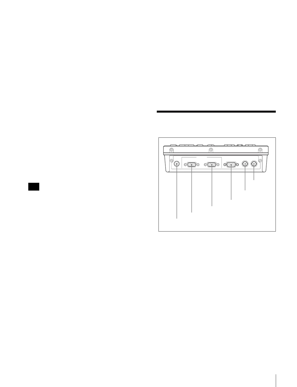
Connector Panel
a DC IN connector (4-pin, male)
Connect the AC adaptor (supplied) or the 9P-4P remote
control cable (supplied). When connected to the HDW-
S280 with a 9P-4P remote control cable, the power is input
to this unit from the HDW-S280.
b RECORDER connector (D-sub 9-pin, female)
Connect to a recorder with the 9P-4P remote control cable
(supplied) or a 9P remote cable (option).
c PLAYER connector (D-sub 9-pin, female)
Connect to a player with the 9P-4P remote control cable
(supplied) or a 9P remote cable (option).
d RS232C (RS-232C) connector (D-sub 9-pin, male)
For maintenance use.
For details on the connector, contact your Sony service
representative.
Note
DC IN
RECORDER
(
DEVICE 1
)
PLAYER
(
DEVICE 2
)
RS232C
REC TALLY
OUTPUT
REF
IN / OUT
REMOTE
(
9P
)
5 REC TALLY
OUTPUT connector
6 REF IN/OUT
connector
1 DC IN connector
2 RECORDER connector
3 PLAYER connector
4 RS232C connector