Performance Verification
F-4
VX4792 User Manual
Table F-1: Test Equipment Requirements (Cont.)
Item Description Recommended InstrumentMinimum Requirements
GPIB Interface National Instruments GPIBĆPC2A
GPIB Cable Tektronix Part Number 012Ć0630Ć06
Performance Check Disk Tektronix Part Number 063Ć1766ĆXX
Precision Termination Impedance: 50ĂW, 0.1%
Connectors: BNC
Tektronix Part Number 011Ć0129Ć00
Adapter Connectors: BNC femaleĆtoĆfemale Tektronix Part Number 103Ć0028Ć00
Adapter Connectors: BNC femaleĆtoĆdual banana Tektronix Part Number 103Ć0090Ć00
BNC Dual Input (TEE) Adapter Connectors: BNC Tektronix Part Number 103Ć0030Ć00
BNC Cable
(4 Required)
Impedance: 50ĂW
Connectors: BNC
Length: 43 inches
Tektronix Part Number 012Ć0057Ć01
Performance Check Disk Waveform Files
The VX4792 Performance Check Disk supplied with your waveform generator
contains files that are used during the Performance Verification procedure.
Table F–2 provides a detailed listing of the contents of each waveform file (.PAT
suffix). Waveform files define the shape, points, clock frequency, and amplitude
of test waveforms. Table F–3 provides a detailed listing of the contents of each
command file (.CMD suffix). Command files are ASCII files that define
instrument settings.
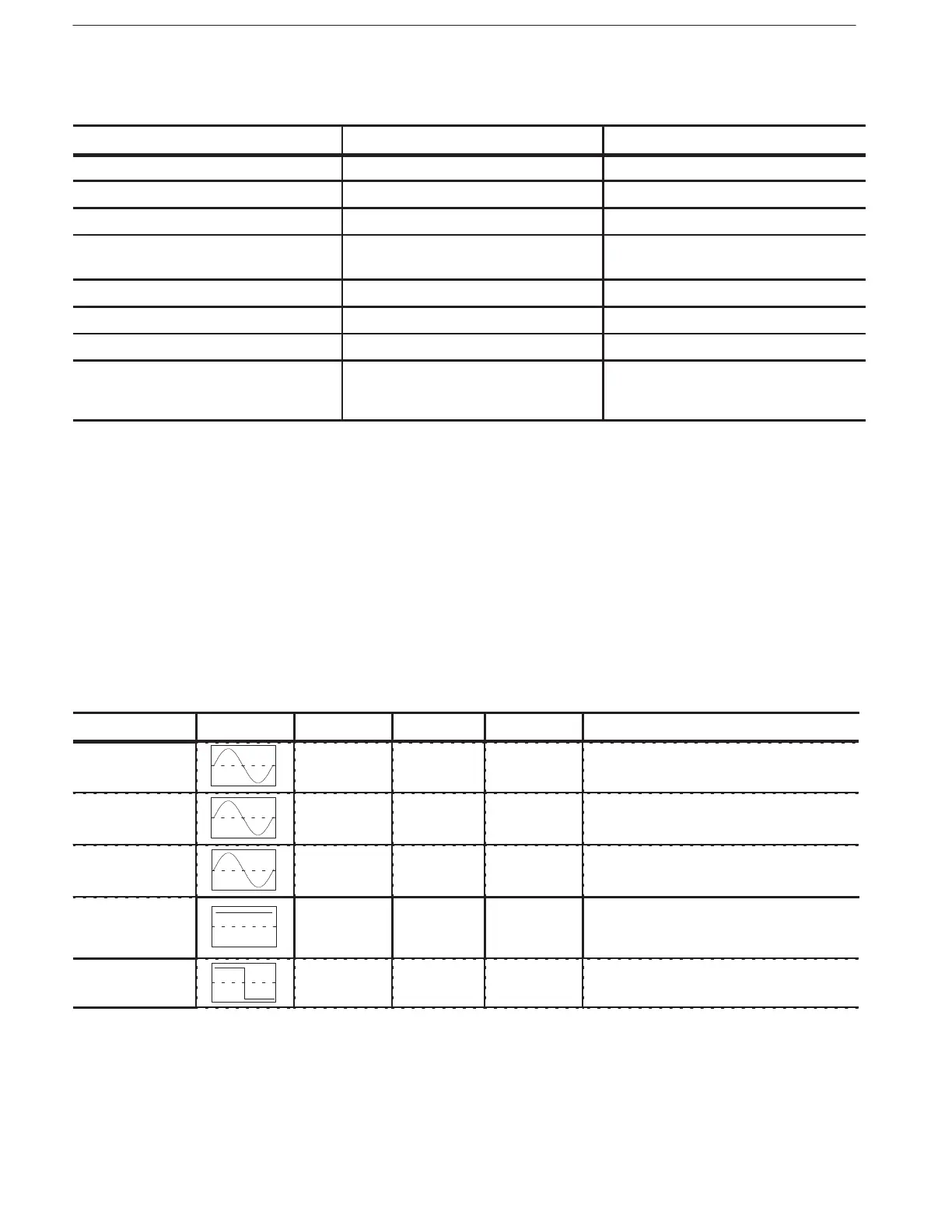
Table F-2: VX4792 Performance Check Disk Waveform File Summary
File Name Wave Shape Points Clock Amplitude Where Used
AST_1.PAT 1000 250 MHz 3 V Autostep Mode
AST_2.PAT 200 150 MHz 1.5 V Autostep Mode
AST_3.PAT 200 25 MHz 0.5 V Autostep Mode
C1000.PAT 1000 100 MHz 1 V Clock Amplitude
DC Amplitude Accuracy
External AM Operation
CLK64.PAT 64 64 MHz 1 V Pulse Response
Synchronous Operation