Performance Verification
VX4792 User Manual
F-13
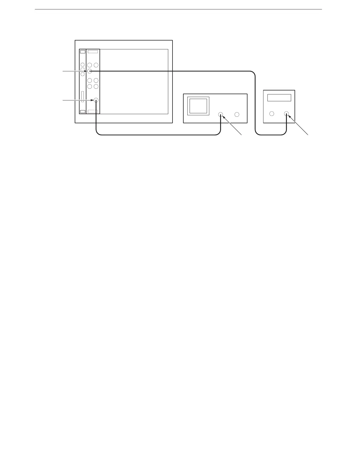
VX4792
Oscilloscope
WAVEFORM
OUTPUT
Ch 1 Input
Function
Generator
Output
TRIGGER
INPUT
Figure F-4: Triggered Mode Initial Test Setup
a. Connect the oscilloscope: Connect the WAVEFORM OUTPUT
connector through the coaxial cable to the CH1 vertical input connector
on the oscilloscope.
b. Connect the function generator: Connect the TRIGGER INPUT
connector though a coaxial cable to the function generator output
connector.
c. Set the oscilloscope controls:
Vertical: CH1
CH1 coupling: DC
CH1 scale 0.2 V/div
CH1 input impedance: 50 W
Horizontal
Sweep 10 ms/div
Trigger
Source CH1
Coupling DC
Slope Positive
Level –100 mV
Mode Auto