Performance Verification
F-42
VX4792 User Manual
v
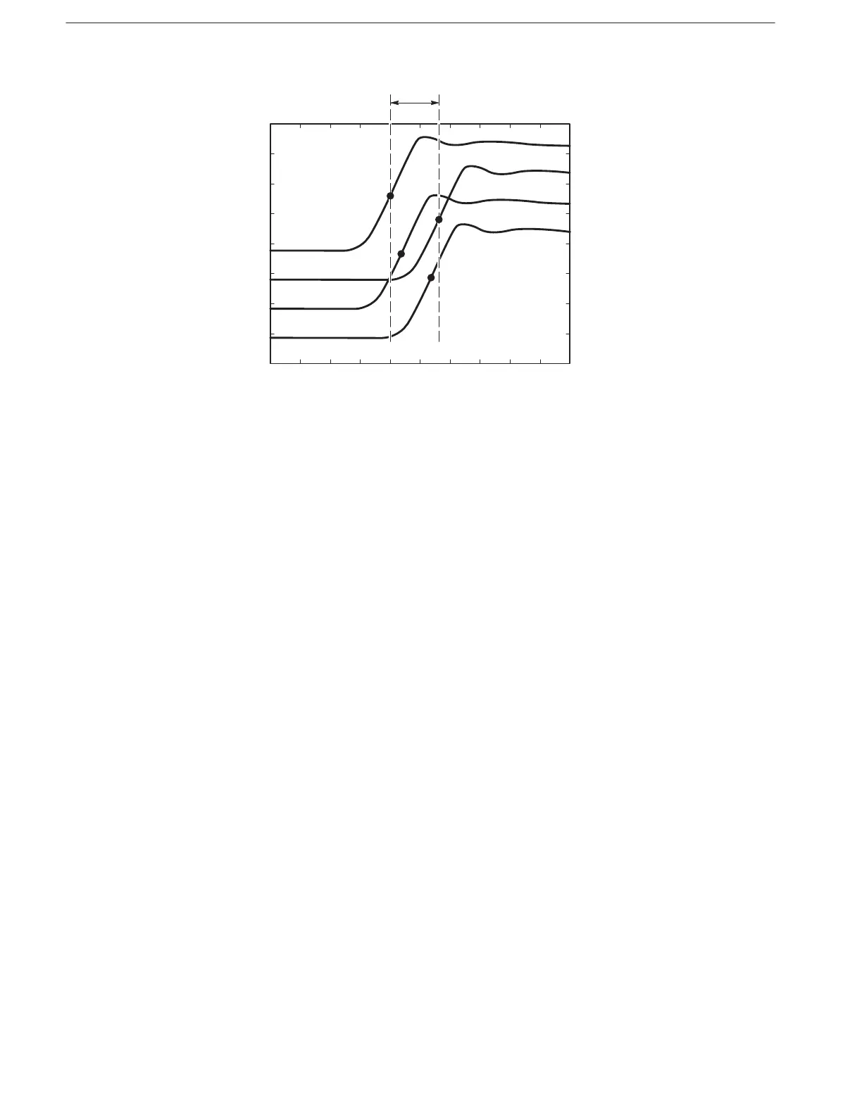
Figure F-20: Skew Between Modules
7. Check skew between the first, second, third, and fifth modules (if installed):
a. Disconnect the coaxial cable from the WAVEFORM OUTPUT of the
fourth module (slots 7 and 8).
b. Connect the coaxial cable to the WAVEFORM OUTPUT of the fifth
module (slots 9 and 10).
c. Check that the skew (time variance) between the rising edges of the
waveforms displayed on the oscilloscope is within 4 ns (see Fig-
ure F–20).
8. Check skew between the first, second, third, and sixth modules (if installed):
a. Disconnect the coaxial cable from the WAVEFORM OUTPUT of the
fifth module (slots 9 and 10).
b. Connect the coaxial cable to the WAVEFORM OUTPUT of the sixth
module (slots 11 and 12).
c. Check that the skew (time variance) between the rising edges of the
waveforms displayed on the oscilloscope is within 4 ns (see Fig-
ure F–20).
9. Turn off equipment and disconnect test setup:
a. Disable equipment: Turn off all equipment.
b. Remove connections: Disconnect all connections to the VX4792
Arbitrary Waveform Generator.