104
Bus fixed mode
Depending on the transition, t
he cross-points of the
background A bus and background B bus do not
interchange.
When the fader lever is at t
he top of its travel, the
background A bus signal is 100% output. When the fader
lever is at the bottom of its travel, background B bus
signal is 100% output.
To execute a manual transition, operate the fader lever in
the direct
ion of the transition as shown below.
Auto transitions are executed regardless of the fader
lever
position.
• When the background and one or more keys (1 to 8) are
ta
rgets of a transition, the transition direction of all
selected background/keys must be the same as the fader
lever operation direction.
• If as a result of an auto transition, the fader lever position
does not match the background/key signal output state, a
non-sync state occurs and LEDs light/flash at both ends
of the transition indicator.
Split fader
Split fader is a function that splits a single fader lever into
left and right, allowing you to control background A bus
and background B bus transitions independently.
The fader lever on the simple-type transition
control
block is split into two by pressing the lock button to
unlock the two fader levers for use as split faders.
The split fader levers sup
port the following buses.
• Right fader lever: Background A bus (main)
• Left fader lever: Background B bus
The split fader function can be enabled/disabled for each
swi
tcher bank. You can also change which is the main
fader lever.
For details about setting spli
t fader, see “Enabling/
Disabling Split Faders” (page 391) and “Setting the
main fader lever when using split faders” (page 413).
The following conditions must be satisfied in order to use
the fader le
ver as split faders.
• Bus fixed mode is set.
• Split faders are enabled.
• Mix or NAM (non-additive mix) is selected for
t
ransition type.
• If the transition type is a clip transition, Mix or NAM
(no
n-additive mix) is selected for the background
transition type.
• If the switcher bank operation mode
is set to multi
program 2 mode, the switcher bank is set to main.
If these conditions are not satisfied, only the main
(ba
ckground A bus) fader lever can be operated.
When not using split fader lever operation, disable split
faders.
If enabled, a black image or super mix image may be
ou
tput when the transition type is changed.
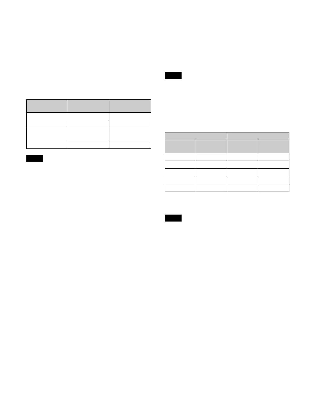
Split fader operation
The relationship between the position of the fader lever
and
the output for a mix transition type is given below.
The A bus and B bus output for a NAM transition type is
an i
mage created using non-additive mixing.
The transition indicator displays the progress of the
backg
round A bus.
Next transition Transition
direction
Fader lever
movement
Background A t B Top t Bottom
B t A Bottom t Top
Key 1 to key 8 On t Of
f
(remove)
Top t Bottom
Off t On (
insert) Bottom t Top
Notes
Note
Fader lever position Output
Right lever
(A bus)
Left lever
(B bus)
A bus B bus
Top Top 100% 0%
Top Bottom 100% 100%
Bottom Top 0% 0%
Bottom Bottom 0% 100%
Center Center 50% 50%
Note