5-20
Initiation
R
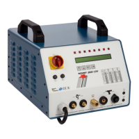
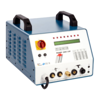
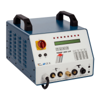
5.2.1 Operating elements
• Main switch (item 2, chapter 5.1)
The main switch is used to switch the stud welder on and off.
• Energy range controller (item 4, chapter 5.1)
The energy range controller enables infinitely variable energy adjustment for
weldable stud diameters.
• Function key for adjusting the lift (item 6, chapter 5.1)
For carrying out the lift test on the welding pistol or welding head, the
charging voltage has to be set to "0" by pressing the function key "Lift
adjustment" (6).
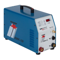
5.2.2 Display elements
• Charging voltage display (item 5, chapter 5.1)
The digital display shows the adjusted energy value
(charging voltage in volts).
• LED displays (item 7, chapter 5.1)
The LEDs show the respective operational states.
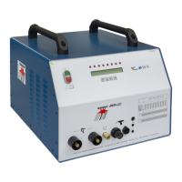
5.2.3 Connecting elements
• Mains connecting cable (item 13, chapter 5.1)
Use the mains connecting cable to connect the stud welder to the power
supply.
• Earth cable connectors (item 12, chapter 5.1)
The earth cable connectors allow the earth terminals to be connected to the
stud welder.
• Control cable connection (item 9, chapter 5.1) and welding cable
socket (item 10, chapter 5.1)
The control cable connection and the welding cable socket serve to connect
the stud welding pistol or the welding head to the stud welder.
SZ.0047.E
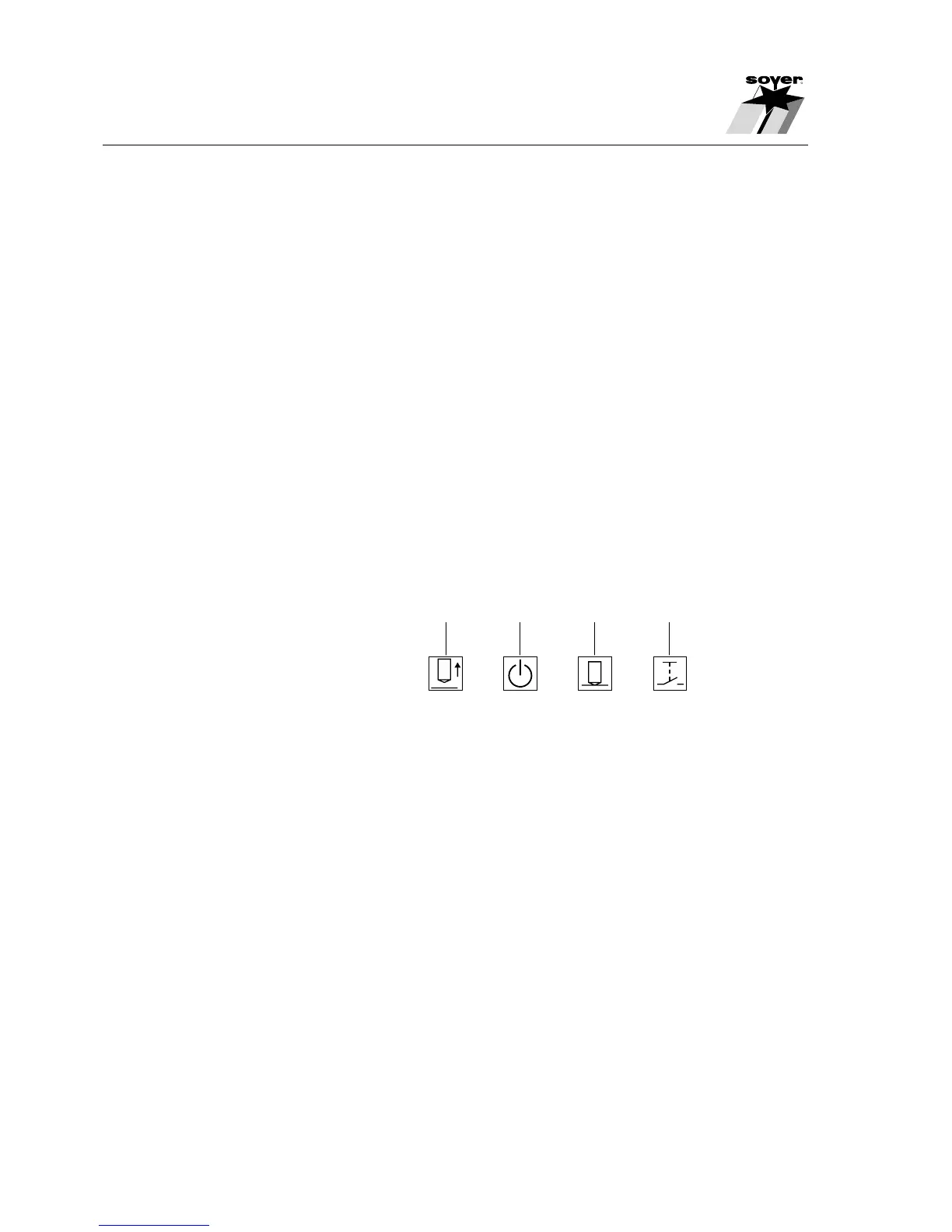
7.1 7.2 7.3 7.4
7.1 LED "Lift"
7.2 LED "Ready"
7.3 LED "Stud on Workpiece"
7.4 LED "Release"