Chapter 7 Parameter Explanation
Shanghai Sigriner STEP Electric Co., Ltd.
- 110 -
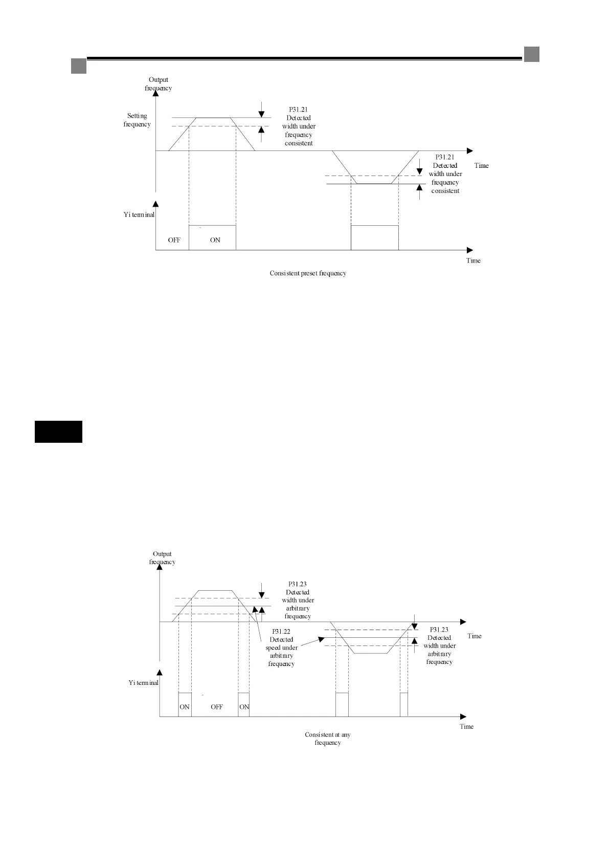
Figure 7-16 Frequency consistency detection 1
P31.22 and P31.23 are used for two parameters detected at any frequency: any frequency detection
width and any frequency detection width. Combination of these two parameters is used for three
functions: frequency/speed consistency, frequency detection 1, and frequency detection 2. Mainly
used to determine whether the output frequency of inverter is within a specified frequency range. In
frequency detection 1, when the inverter output frequency arrives or exceeds the value of frequency
detection speed (P31.22) plus frequency detection width (P31.23), frequency detection 1 is triggered;
after corresponding output point action, when the inverter output frequency drops back to the
frequency detection speed (P31.22), frequency detection 1 resets. Frequency detection 1 is negative
logic, when triggered, the corresponding output status is OFF; when reset, the corresponding output
status is ON.
In frequency detection 2, when the inverter output frequency arrives or exceeds the value of
frequency detection speed (P31.22), frequency detection 2 is triggered; after corresponding output
point action, when the inverter output frequency drops back to the value of frequency detection
speed (P31.22) minus frequency detection width (P31.23), frequency detection 2 resets. Frequency
detection 2 is positive logic, when triggered, the corresponding output status is ON; when reset, the
corresponding output status is OFF.
Set output terminal function to "5: Frequency/speed consistency", as shown in the following figure.
Figure 7-17 Frequency consistency detection 2



 To Next Page