2-3
Installation Checklist Operator Manual 122997-341
❑ Washer is positioned, as shown on equipment drawing, with
required service clearance space and in relation to building sup-
ply lines.
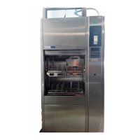
❑ Basil 4600 Cage and Rack Washer and Basil 4602 Cage and
Rack Washer must be installed between two walls, with a key-
locked service door, so washer service side is not accessible to
operator.
❑ Building steam line provides maximum dynamic steam pressure
and flow rate to washer as specified on equipment drawing.
❑ Drip leg with steam trap installed in steam supply line.
❑ Building hot water line supplies water to washer at pressure and
temperature specified on equipment drawing.
❑ Building cold water line supplies water to washer at pressure
specified on equipment drawing.
❑ Electrical supply for washer is as specified on equipment draw-
ing.
❑ Condensate returns are sized as specified on equipment draw-
ing.
❑ Vent connections are sized as specified on equipment drawing.
❑ Recirculation pump pressure is within 25 to 60 psig.
❑ Recirculation pump motor rotating in direction shown by arrow.
❑ Self-cleaning screen assembly functioning properly.
❑ Carriage drive motor rotating in direction shown by arrow.
❑ Carriage drive system functioning properly.
❑ Carriage drive motor amperage within rating indicated on the
motor.
❑ Optional exhaust fan rotating in direction shown by arrow.
❑ All piping is leak-free.
❑ Chamber sump steam coil functioning properly.
❑ Door safety switch(es) functioning properly.
❑ Cabinet joints are completely sealed, no leaks (for verification,
run machine for 1/2 hour).
❑ Door(s) easily opens from inside of chamber.
❑ Safety cables immediately stop washer operation when pulled.
❑ Each gear box plastic cap removed and replaced with air vent
provided.
❑ Floor surrounding unit has non-slip surface.
IMPORTANT: After a few weeks of operation, inspect unit for leaks.
Retighten all clamps and connections.
 Loading...