STÖBER 4 | Drive controller technical data
11/2017 | ID 442793.00
15
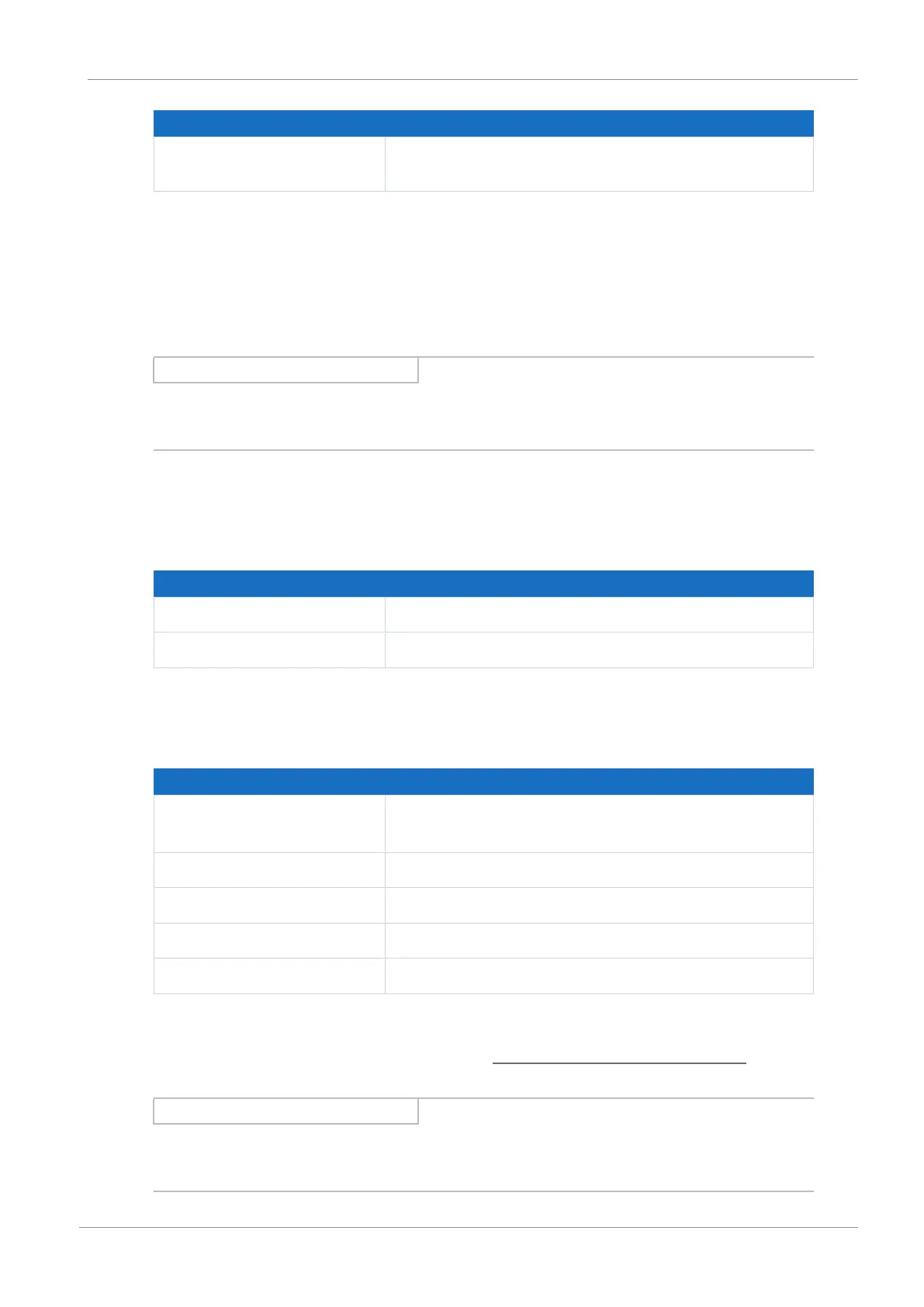
Discharge times
Self-discharge of DC
intermediate circuit
5min
Tab. 5: Discharge times of the DC link circuit
4.2 Electrical data
The electrical data of the available SC6 sizes as well as the properties of the brake chopper can
be found in the following sections.
Information
Direct, repeat activation of the supply voltage is possible for cyclical line on/line off operation in
the event that charging capacity is not increased.
An explanation of the symbols used for formulas can be found in Chapter Symbols in formulas.
4.2.1 Control unit
Electrical data All types
U
1CU
24V
DC
, +20%/−15%
I
1maxCU
0.5A
Tab. 6: Control unit electrical data
4.2.2 Power unit: Size 0
Electrical data SC6A062
U
1PU
3 × 400 V
AC
, +32% / −50%, 50/60 Hz;
3 × 480 V
AC
, +10% / −58%, 50/60 Hz
f
2PU
0 – 700 Hz
U
2PU
0 – max. U
1PU
C
PU
270µF
C
maxPU
1400µF
Tab. 7: SC6 electrical data, size 0
The maximum charging capacity depends on the time between energizing two devices
:
Information
If a time span of ≥ 15min is maintained between energizing two devices, the maximum charging
capacity C
maxPU
increases to 1880μF.

 Loading...


