STÖBER 7 | Connection
11/2017 | ID 442793.00
57
7.4.20 X300: Brake 24V supply
X300 is used to supply the brake.
ATTENTION!
Device damage due to overload!
If the 24 V
DC
power supply is looped to multiple devices over the terminal, the terminal may be
damaged by a current that is too high.
▪ Make sure that the current over the terminal does not exceed the value 15A (UL: 10A).
Electrical data Single-axis controller Double-axis controller
U
1
+24V
DC
, +25%/−0%
I
1max
2.5A 2 × 2.5A
Tab. 62: Electrical data of the control unit brake control
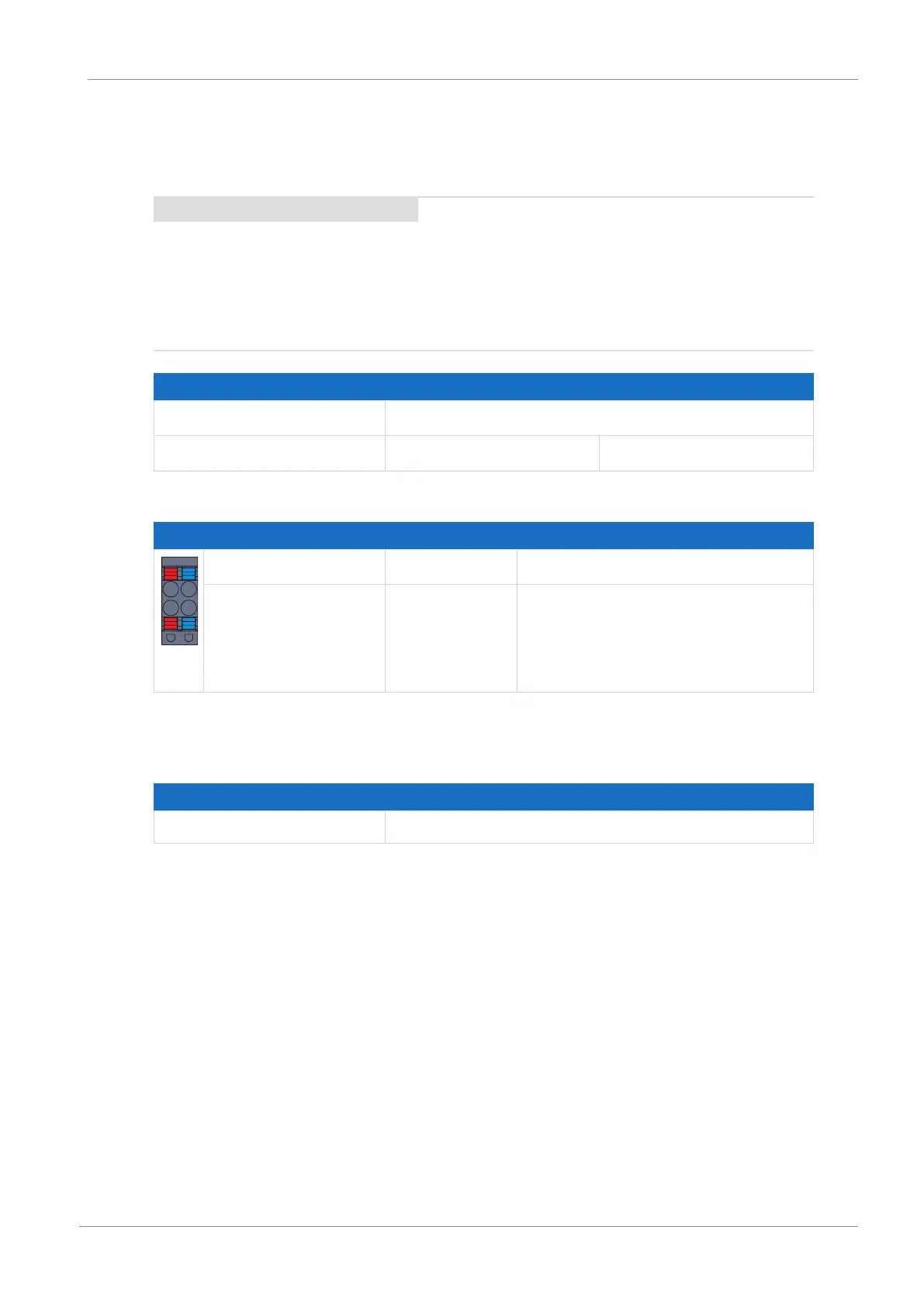
Pin Designation Function
+ | −
+ +24V
DC
Power supply voltage for the brake
− GND Reference potential for supply voltage of
the brake
Tab. 63: X300 connection description
Cable requirements
Feature All sizes
Max. cable length 30m
Tab. 64: Cable length [m]

 Loading...


