7 | Connection STÖBER
36
11/2017 | ID 442793.00
7.3.3 Housing grounding
Additional requirements for protective equipotential bonding apply in the event of ground
leakage currents > 10mA. At least one of the following conditions must be fulfilled:
§ The grounding conductor must have a minimum cross-section of 10mm² Cu over its overall
length
§ If the grounding conductor has a cross-section of less than 10mm², a 2nd grounding
conductor must be provided with a cross-section of at least the same size up to the point at
which the grounding conductor exhibits the minimum cross-section of 10mm²
A grounding bolt is mounted to the devices for connecting the 2nd grounding conductor.
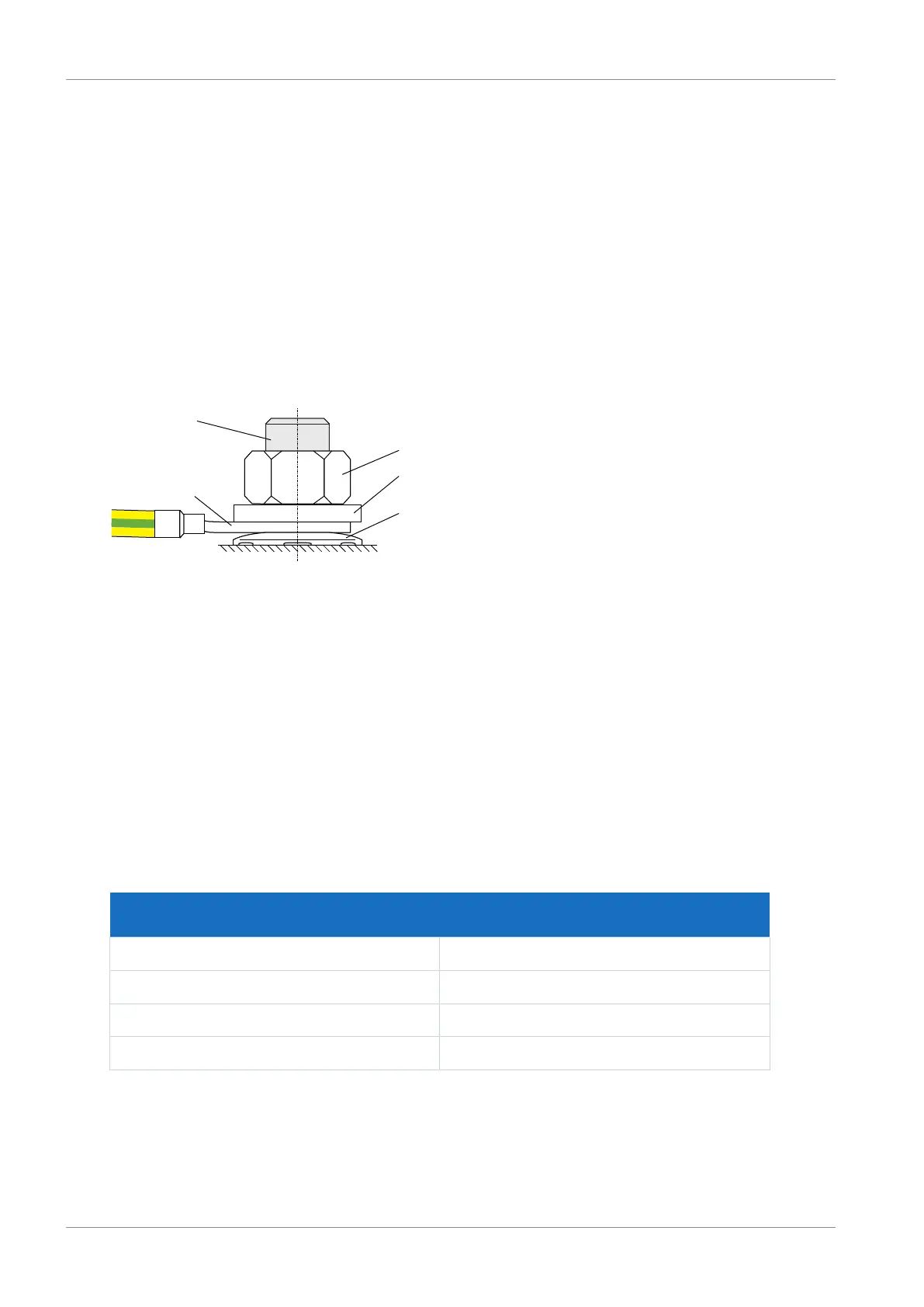
Observe the order for assembly:
Fig.5: Connection of the grounding conductor
1 M6 grounding bolt
2 Contact disk
3 Cable lug
4 Washer
5 Nut
The contact disk, washer and nut are supplied with the drive controller.
Note the tightening torque of 4Nm.
Leakage currents > 10mA can arise in normal operation. To fulfill DIN EN 61800-5-1 and EN
60204-1, connect the grounding bolt with a copper conductor according to the following table:
Cross-section A
Power grid line
Minimum cross-section A
min
Grounding conductor at grounding bolt
A ≤ 2.5 mm² 2.5 mm²
2.5 < A ≤ 16 mm² A
16 – 35 mm² ≥ 16 mm²
> 35 mm² A/2
Tab. 24: Minimum cross-section of the grounding conductor

 Loading...


