7 | Connection STÖBER
52
11/2017 | ID 442793.00
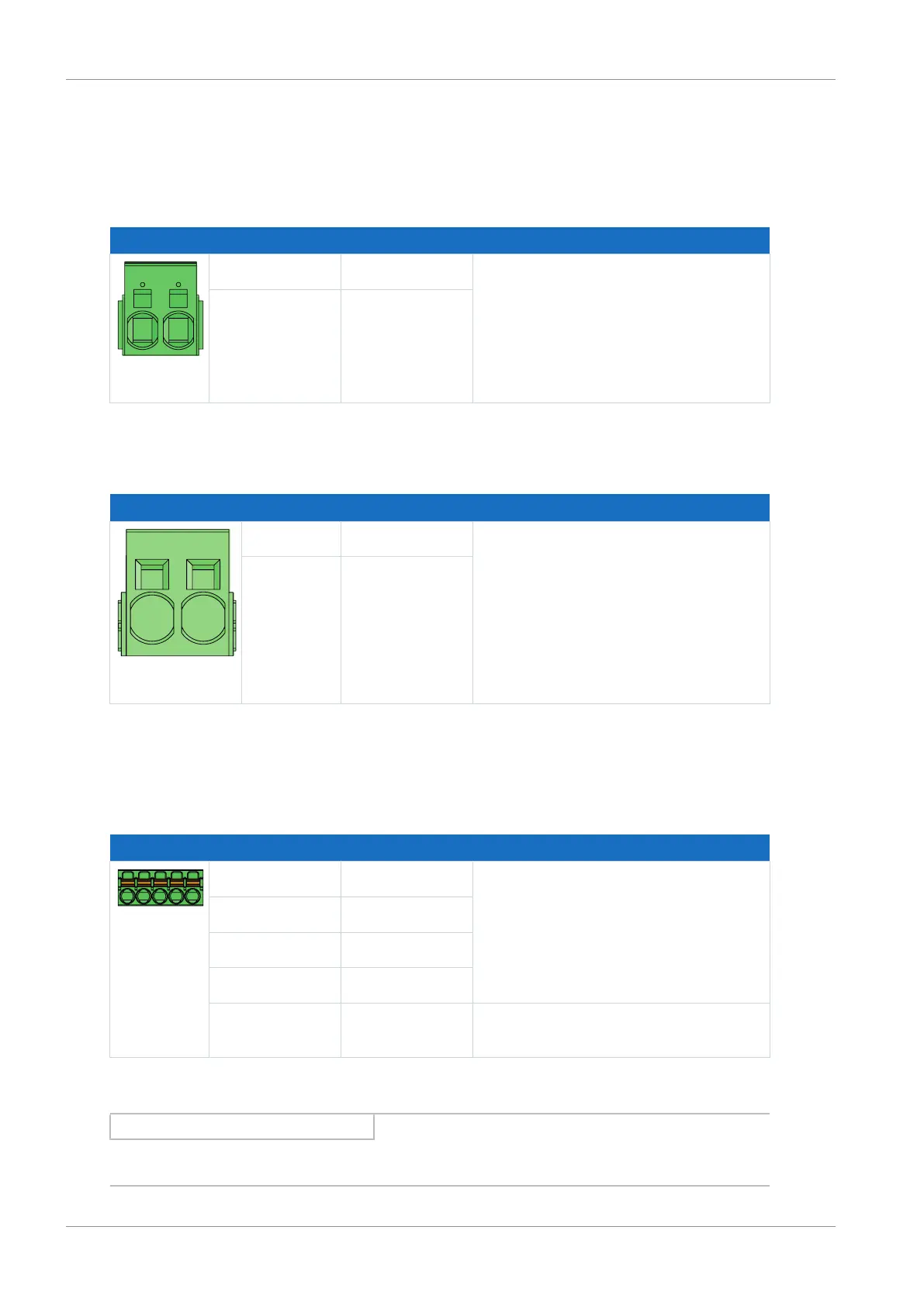
7.4.15 X22: DC link connection
Terminal X22 is available for the DC link connection of the drive controller.
Size 0
Terminal Pin Designation Function
D− | D+
1 D− DC link connection
2 D+
Tab. 50: X22 connection description – Size 0
Sizes 1 and 2
Terminal Pin Designation Function
D− | D+
1 D− DC link connection
2 D+
Tab. 51: X22 connection description – Sizes 1 and 2
7.4.16 X101: BE1 – BE4
The binary inputs 1 to 4 are available on terminal X101.
Terminal Pin Designation Function
5|4|3|2|1
1 BE1 Binary inputs
2 BE2
3 BE3
4 BE4
5 DGND Reference ground; not bridged with
X103, pin 5
Tab. 52: X101 connection description for binary signals
Information
Note that a master encoder must be connected to axis A or terminal X101.

 Loading...


