STÖBER 7 | Connection
11/2017 | ID 442793.00
53
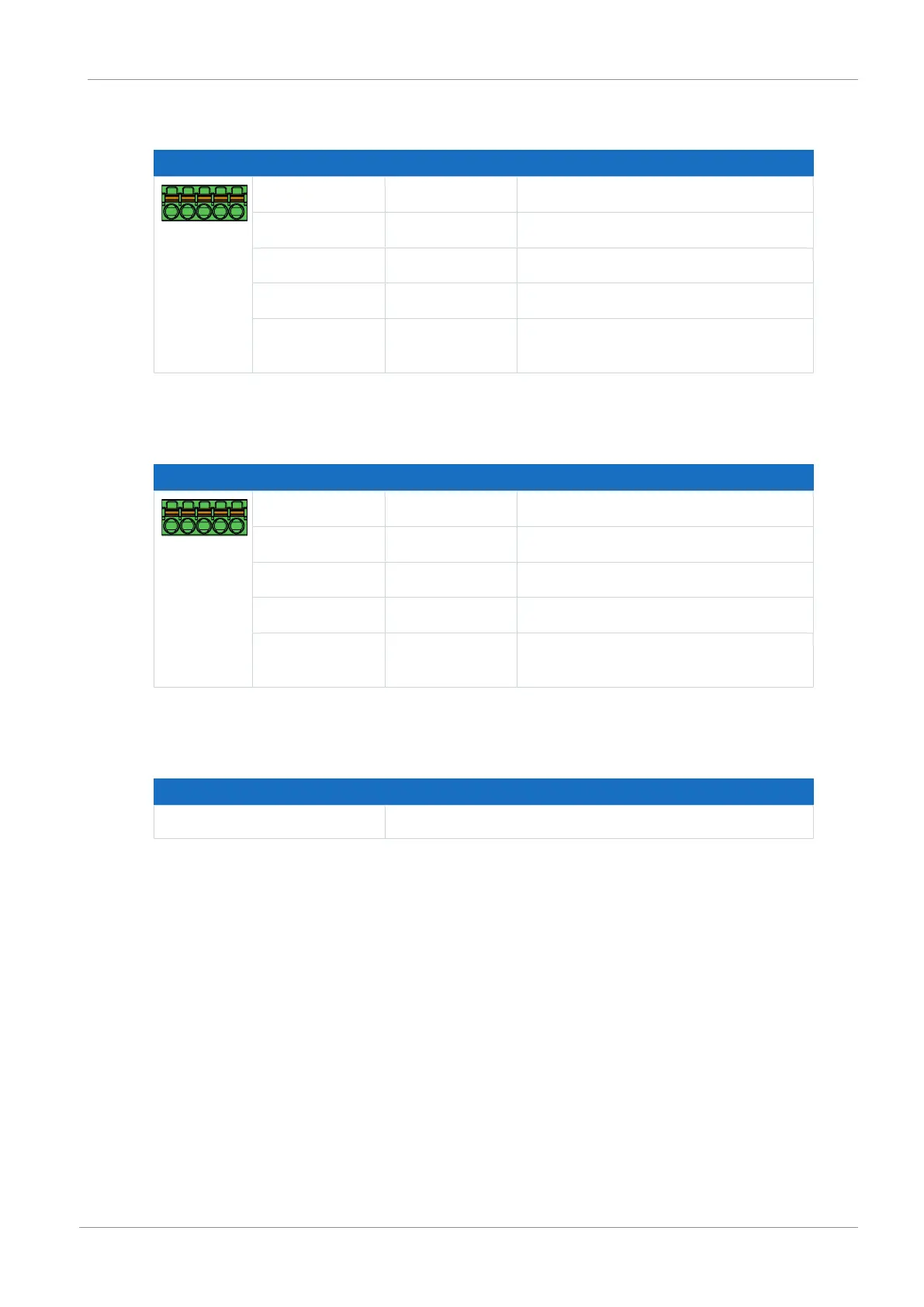
Single-ended HTL incremental encoders
Terminal Pin Designation Function
5|4|3|2|1
1 BE1 —
2 BE2 N channel
3 BE3 A channel
4 BE4 B channel
5 DGND Reference ground; not bridged with
X103, pin 5
Tab. 53: X101 connection description for single-ended HTL incremental signals – Axis A
Single-ended HTL pulse train
Terminal Pin Designation Function
5|4|3|2|1
1 BE1 —
2 BE2 —
3 BE3 Frequency
4 BE4 Direction
5 DGND Reference ground; not bridged with
X103, pin 5
Tab. 54: X101 connection description for single-ended HTL pulse train signals – Axis A
Cable requirements
Feature All sizes
Max. cable length 30m
Tab. 55: Cable length [m]

 Loading...


