7 | Connection STÖBER
48
11/2017 | ID 442793.00
7.4.10 X11: 24V supply
The connection of 24V
DC
to X11 is required for the power supply of the control unit.
ATTENTION!
Device damage due to overload!
If the 24 V
DC
power supply is looped to multiple devices over the terminal, the terminal may be
damaged by a current that is too high.
▪ Make sure that the current over the terminal does not exceed the value 15A (UL: 10A).
Electrical data All types
U
1CU
24V
DC
, +20%/−15%
I
1maxCU
0.5A
Tab. 40: Control unit electrical data
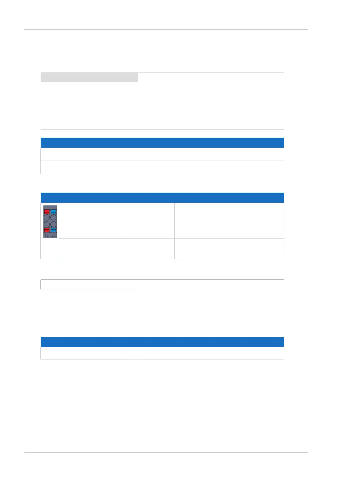
Pin Designation Function
+ | −
+ +24V
DC
24V
DC
supply of the control unit, bridged
in the terminal; design in accordance
with EN 60204: PELV, secondary
grounded
− GND Reference potential for +24V
DC
, bridged
in the terminal
Tab. 41: X11 connection description
Information
The device may not be connected to a DC supply grid. Instead, supply it over a local 24 V
DC
power supply.
Cable requirements
Feature All sizes
Max. cable length 30m
Tab. 42: Cable length [m]

 Loading...


