STÖBER 9 | Appendix
11/2017 | ID 442793.00
69
9 Appendix
9.1 Wiring examples
The following chapters show the basic connection using examples.
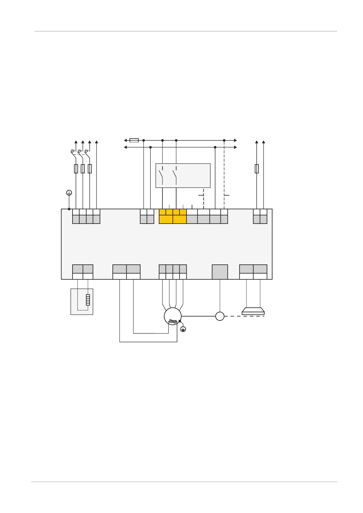
9.1.1 Stand-alone operation with direct brake control
The following graphic shows a wiring example for stand-alone operation with direct brake
control.
SC6
X10
GND
STO_a STO_b
GND
Vc
L1 L2
L3
PE
1 2
3
4
1 2
3
4
5
6 7 8
X11
+
-
1 2
F3
K1
M
24 V
DC
X300
+
-
1
2
T1
PEL1 L2
L3
F2
F1
24 V
DC
M
F4
1
X20A
X4A
X2A
1TP1 1TP2
U
V W PE
7
8
1 2
3
4
n
X2A
1BD1 1BD2
5
6
R1
1 2
RB RB
1 2
3
4
M
M1
X21
1
STO
status
X12 (ST6 option)
Direct
brake
control
D-sub
15p
Fig.7: Wiring example with direct brake control
F1 – F4 Fuse
K1 Safety relay
L1 – L3 Three-phase power supply
M Reference ground
M1 Motor
R1 Braking resistor
T1 Supply module
T2 Drive controller
1 Optional connection
2 Spring-loaded contact between DL6B and SC6

 Loading...


