STÖBER 7 | Connection
11/2017 | ID 442793.00
47
7.4.9 X10: 400V supply
Terminal X10 serves to connect the drive controller to the supply grid.
Line cross-section for the power connection
When selecting your line fuse, note the maximum permitted conductor cross-section of terminal
X10, the routing method and the surrounding temperature.
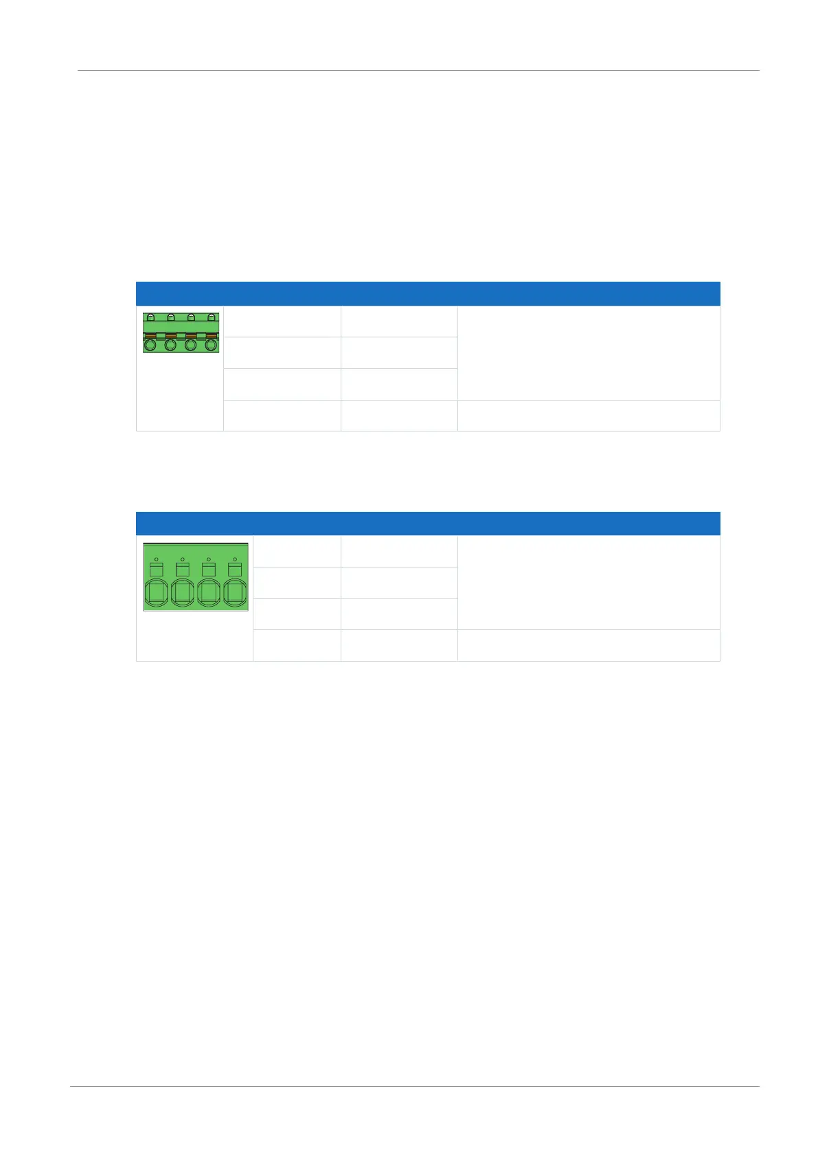
Size 0
Terminal Pin Designation Function
L1 | L2 | L3 |
PE
1 L1 Power supply
2 L2
3 L3
4 PE Grounding conductor
Tab. 38: X10 connection description – Size 0
Sizes 1 and 2
Terminal Pin Designation Function
L1 | L2 | L3 | PE
1 L1 Power supply
2 L2
3 L3
4 PE Grounding conductor
Tab. 39: X10 connection description – Size 1 and 2

 Loading...


