EasyManuals Logo

Stober SC6 Series Commissioning Instructions

Stober SC6 Series
74 pages
To Next Page IconTo Next Page
To Previous Page IconTo Previous Page
Page #26 background imageLoading...
Page #26 background image
6 | Installation STÖBER
26
11/2017 | ID 442793.00
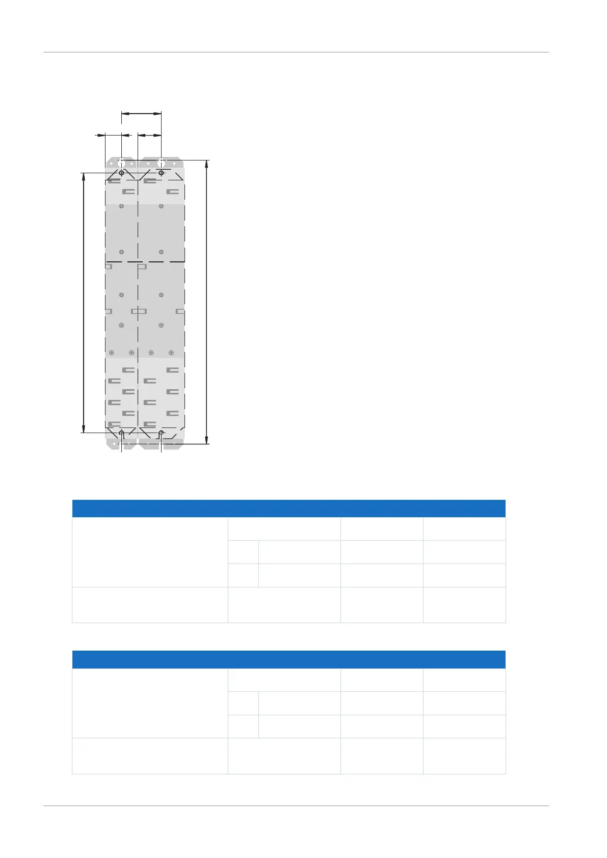
6.4 Drilling diagram and dimensions
D
0
1 – 2
C
B
A/2 A/2
Fig.3: Bore dimensions for DL6B Quick DC-Link [mm]
SC6 dimensions Size0 Size 1, size2
Horizontal SC6 fastening holes
4.2 (M5)
A 45 65
B Size0 46±1 56±1
B Size1, size 2 56±1 66±1
Vertical SC6 fastening holes
4.2 (M5)
C 360+2 360+2
Tab. 20: Bore dimensions for SC6 drive controller [mm]
DL6B dimensions Size0 Size 1, size2
Horizontal fastening holes
4.2 (M5)
A 45 65
B Size0 46±1 56±1
B Size1, size 2 56±1 66±1
Vertical fastening holes
4.2 (M5)
D 393+2 393+2
Tab. 21: Bore dimensions for DL6B Quick DC-Link [mm]

Table of Contents

Other manuals for Stober SC6 Series

Questions and Answers:

Question and Answer IconNeed help?

Do you have a question about the Stober SC6 Series and is the answer not in the manual?

Stober SC6 Series Specifications

General IconGeneral
BrandStober
ModelSC6 Series
CategoryController
LanguageEnglish

Related product manuals