7 | Connection STÖBER
54
11/2017 | ID 442793.00
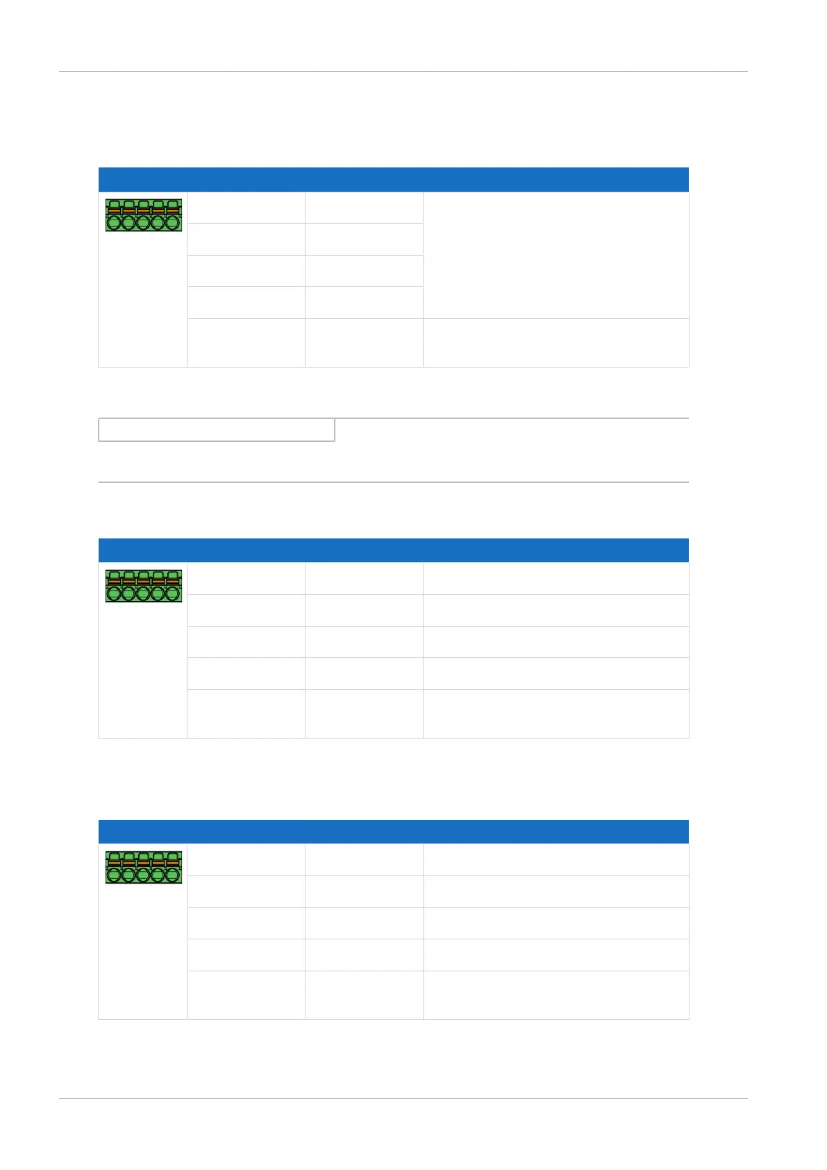
7.4.17 X103: BE6 – BE9
The binary inputs 6 to 9 are available on terminal X103.
Terminal Pin Designation Function
5|4|3|2|1
1 BE6 Binary inputs
2 BE7
3 BE8
4 BE9
5 DGND Reference ground; not bridged with
X101, pin 5
Tab. 56: X103 connection description for binary signals
Information
Note that a master encoder must be connected to axis A or terminal X101.
Single-ended HTL incremental encoders
Terminal Pin Designation Function
5|4|3|2|1
1 BE6 —
2 BE7 N channel
3 BE8 A channel
4 BE9 B channel
5 DGND Reference ground; not bridged with
X101, pin 5
Tab. 57: X103 connection description for single-ended HTL incremental signals – Axis B
Single-ended HTL pulse train
Terminal Pin Designation Function
5|4|3|2|1
1 BE6 —
2 BE7 —
3 BE8 Frequency
4 BE9 Direction
5 DGND Reference ground; not bridged with
X101, pin 5
Tab. 58: X103 connection description for single-ended HTL pulse train signals – Axis B

 Loading...


