1A-33 Engine General Information and Diagnosis:
DTC “C14” (P0120-H/L): TP Sensor Circuit Malfunction
B931H21104012
Detected Condition and Possible Cause
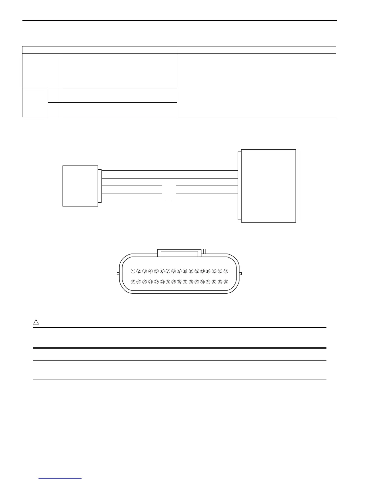
Wiring Diagram
ECM coupler (Harness side)
Troubleshooting
CAUTION
!
When using the multi-circuit tester, do not strongly touch the terminal of the ECM coupler with a
needle pointed tester probe to prevent the terminal damage or terminal bend.
NOTE
After repairing the trouble, clear the DTC using SDS tool. Refer to “Use of SDS Diagnosis Reset
Procedures (Page 1A-12)”.
Detected Condition Possible Cause
C14
Output voltage is not within the following
range.
0.2 V ≤ Sensor voltage < 4.8 V
• TP sensor maladjusted.
• TP sensor circuit open or short.
• TP sensor malfunction.
• ECM malfunction.
P0120
H
Sensor voltage is higher than specified
value.
• TP sensor circuit is shorted to VCC or ground circuit
open.
L
Sensor voltage is lower than specified
value.
• TP sensor circuit is open or shorted to the ground or
VCC circuit open.
B/Br
Y
R
ECM
TP sensor
E2
TP
VCC
6
14
24
I931H1110027-02
I831G1110019-01

 Loading...


