5A-10 Automatic Transmission:
5) Assemble the movable plate (4) to the movable drive
face (2).
6) Apply grease to the inside groove of the spacer (5).
: Grease 99000–25010 (SUZUKI SUPER
GREASE A or equivalent)
7) Install the spacer (6).
NOTE
When installing the spacer, press down the
movable drive face plate so as not to cause
the rollers to come out of position.
Movable Driven Face Disassembly and
Assembly
B931H25106007
Refer to “Automatic Transmission Components
(Page 5A-3)” and “V-belt Type Continuously Variable
Automatic Transmission Removal and Installation
(Page 5A-5)”.
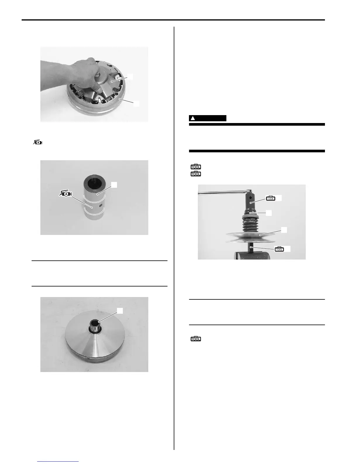
Disassembly
1) Hold the driven face assembly (1) with the special
tool and vise, loosen the movable driven face ring
nut (2) with the special tool.
WARNING
!
Do not remove the movable driven face ring
nut before attaching the clutch spring
compressor.
Special tool
(A): 09917–23711 (Ring nut socket wrench)
(B): 09924–52450 (Fixed driven face holder)
2) Set the special tool to the driven face assembly (1)
and compress the driven face assembly by turning in
the special tool handle.
NOTE
Make sure to insert the spring end “A” into
the slot “B” of the special tool as shown in
the figure.
Special tool
(C): 09922–31430 (Clutch spring
compressor)
4
2
I931H1510029-02
5
I831G1510032-02
6
I931H1510030-01
(A)
2
1
(B)
I931H1510031-01

 Loading...


