4A-1 Brake Control System and Diagnosis:
Brake
Brake Control System and Diagnosis
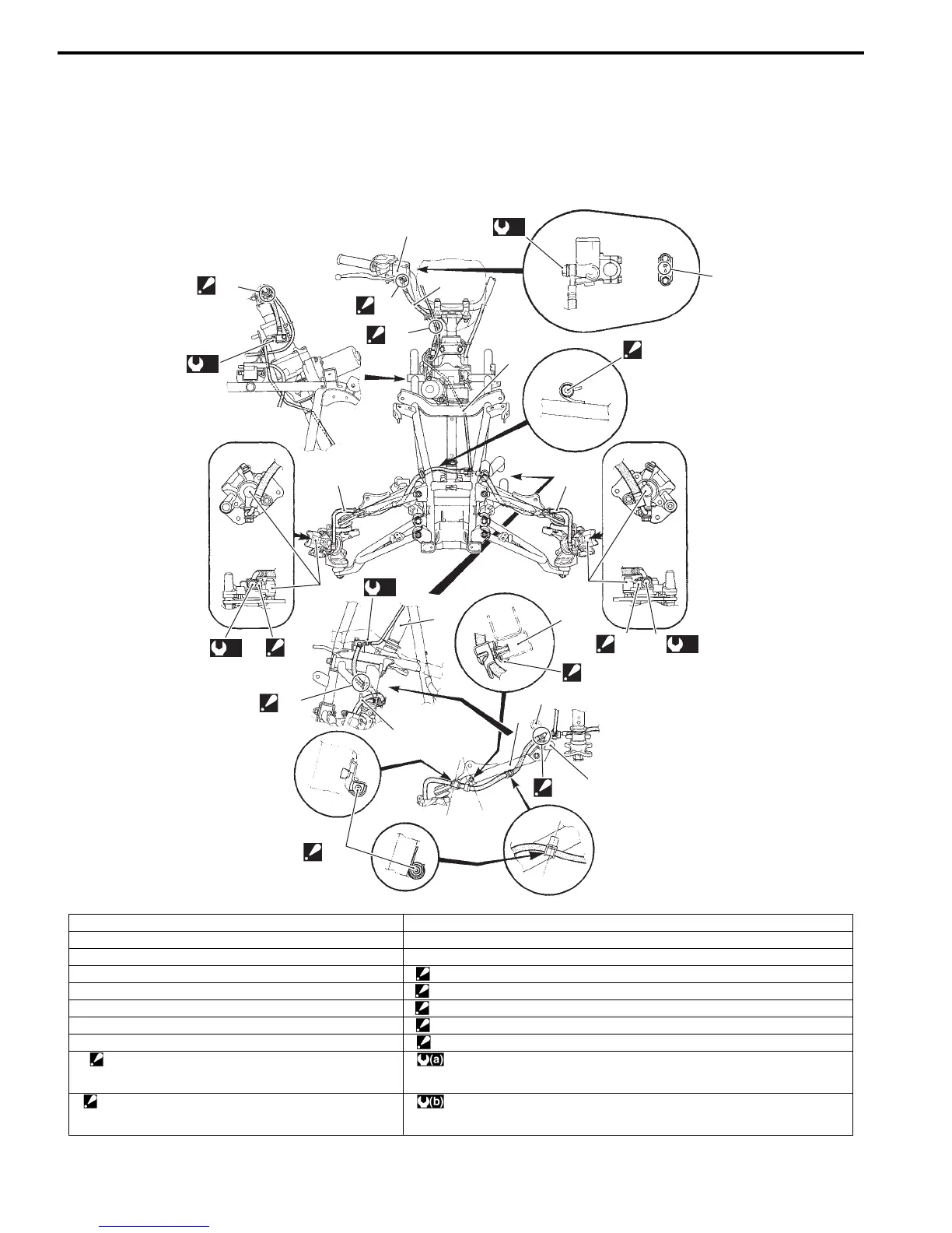
Schematic and Routing Diagram
Front Brake Hose Routing Diagram
B931H24102001
1
“B”
2
“C”
3
4
5
5
7
4
(a)
8
9
4
(a)
8
9
10
11
11
12
(a)
8
11
“E”
6
“F”
(b)
“D”
(b)
“A”
“D”
“D”
I931H1410043-05
1. Master cylinder 11. Suspension upper arm
2. Front brake hose No. 1 12. Radiator hose
3. Front brake pipe “A”: UP mark.
4. Front brake hose No. 2 “B”: After the brake hose union has contacted the reservoir bottom.
5. Front brake caliper “C”: Pass the brake hose behind the throttle cable.
6. Frame “D”: Fix the brake hose to the it guide firmly.
7. Steering shaft “E”: Pass the brake hose No. 2 between the radiator lower hose and frame.
8. Union bolt “F”: Pass the brake hose inside of the suspension arm.
9. Stopper
: After the brake hose union has contacted the stopper,
tighten the union bolt.
: 23 N⋅m (2.3 kgf-m, 16.5 lbf-ft)
10. Stopper
: After the brake hose clamp has contacted the
suspension upper arm, tighten the stopper bolt.
: 16 N⋅m (1.6 kgf-m, 11.5 lbf-ft)

 Loading...


