Automatic Transmission: 5A-25
Installation
Install the gear shift lever in the reverse order of
removal. Pay attention to the following points:
• Apply grease to pivot.
: Grease 99000–25010 (SUZUKI SUPER
GREASE A or equivalent)
• Apply thread lock to the shift lever assembly mounting
bolts.
: Thread lock cement 99000–32050
(THREAD LOCK CEMENT 1342 or equivalent)
• Install the gear shift arm (1) to the gear shift shaft in
the correct position.
• Tighten the bolt (2) securely.
CAUTION
!
Make sure the operating angle of the gear
shift arm is accurate.
• Install the removed parts. Refer to “Front Side Exterior
Parts Removal and Installation in Section 9D
(Page 9D-6)”.
Shift Lever Disassembly and Assembly
B831G25106019
1) Removed the shift lever assembly. Refer to “Shift
Lever Assembly Removal and Installation (Page 5A-
24)”.
2) Disassemble the shift lever assembly as shown in
the shift lever components. Refer to “Shift Lever
Assembly Components (Page 5A-23)”.
Assembly
1) Assemble the shift lever as shown in the shift lever
components. Refer to “Shift Lever Assembly
Components (Page 5A-23)”.
2) Install the shift lever assembly. Refer to “Shift Lever
Assembly Components (Page 5A-23)”.
3) After Installing the gear shift lever assembly, adjust
the shift rod. Refer to “Shift Rod Adjustment
(Page 5A-25)”.
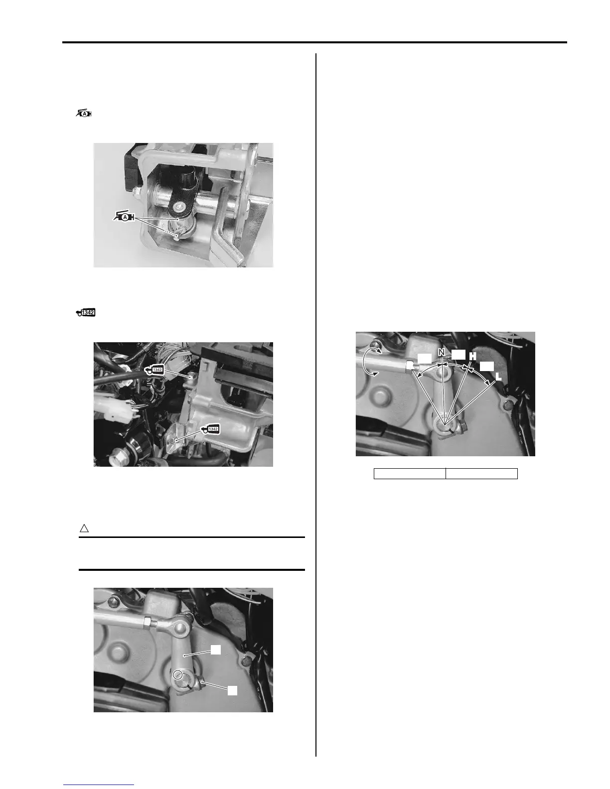
Shift Rod Adjustment
B831G25106020
1) Holding the rod (2), loosen the lock-nuts (1).
2) Turning the rod (2), adjust the length of the rod.
3) Tighten the lock-nuts (1).
I831G1510107-03
I831G1510108-02
2
1
I831G1510109-01
“a”: 30° “b”: 33°
R
L
H
“a”
“b”
“b”
I831G1510110-03
 Loading...


