ENGINE 3-65
PAIR (AIR SUPPLY) SYSTEM
PAIR HOSE
INSPECTION
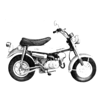
• Inspect the PAIR hoses for wear or damage.
• Inspect the PAIR hoses are securely connected.
PAIR CONTROL VALVE
REMOVAL
• Disconnect the hoses and remove the PAIR control valve
1.
INSPECTION
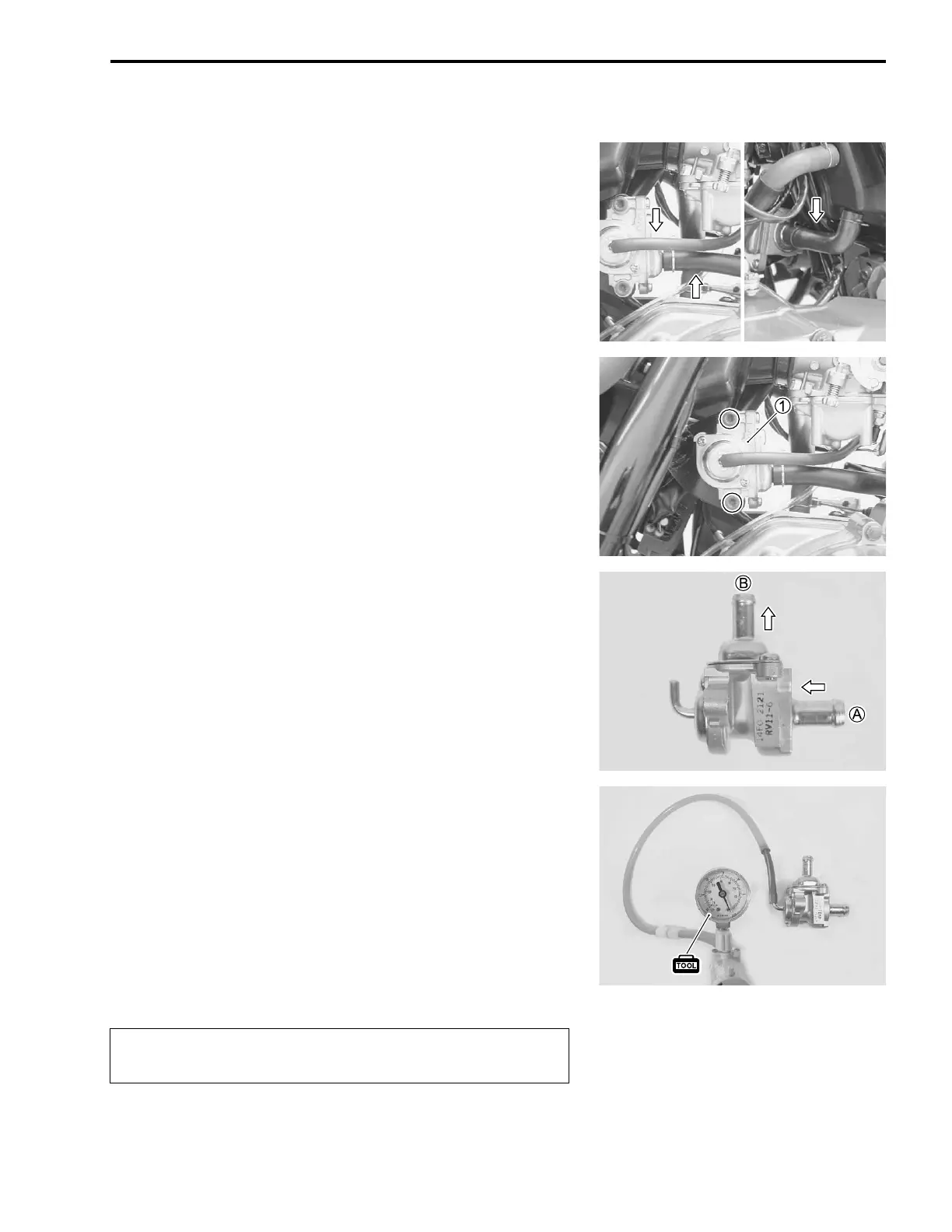
• Inspect that air flows through the PAIR control valve air inlet
port
A to the air outlet port
B. If air does not flow out, replace
the PAIR control valve with a new one.
• Connect the vacuum pump gauge to the vacuum port of the
control valve as shown in the photograph.
• Apply negative pressure slowly to the control valve and
inspect the air flow. If air does not flow out, the control valve
and is in normal condition. If the control valve does not func-
tion, replace it with a new one.
$ Negative pressure range:
–37.3 – –60.0 kpa (–280 – –450 mmHg)
% 09917-47010: Vacuum pump gauge
"
INSTALLATION
Installation is in the reverse order of the removal.
Use a hand operated vacuum pump to prevent the
control valve damage.

 Loading...