17. ELECTRICAL SYSTEM
17-8
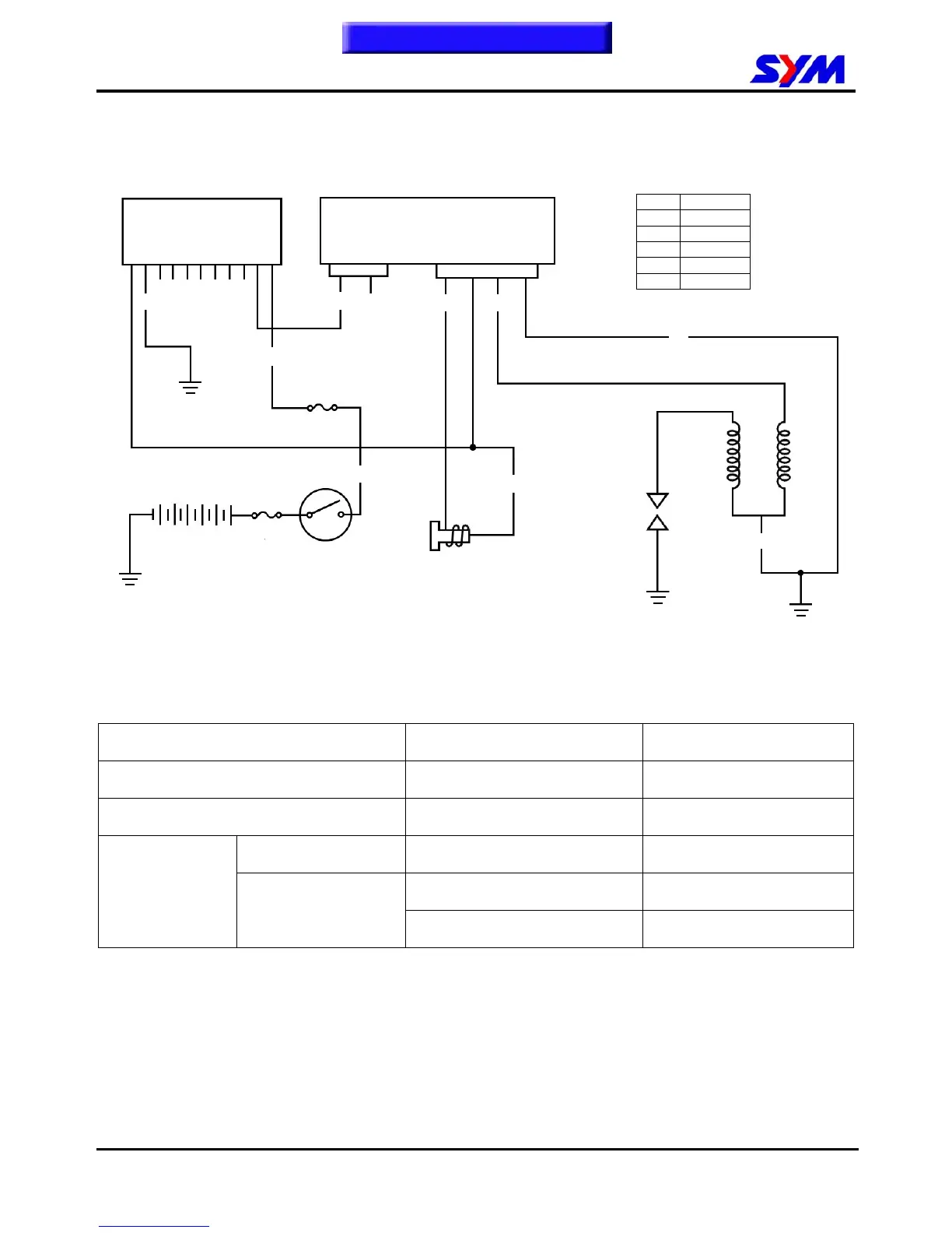
Ignition System
Ignition circuit diagram
C.D.I unit
Disconnect connectors of the C.D.I unit.
Check the following connectors as indicated in the table at the harness side.
Item Points to check Result
Main switch turn to “ON” position Black/white ~ green Battery voltage
Pulse generator Green/White ~ Blue/yellow 50~170Ω
Primary circuit Black/yellow ~ green
0.17±10%Ω
Black/yellow ~ with no cap
3.6±10%Ω
Ignition coil
Secondary circuit
Black/yellow ~ with cap 7.3~11KΩ
Main switch
Shift gear control unit
Pulse generator
Spark plug
Ignition
coil
CDI. Unit
G
B/Y
G
W/B
G/W
L/Y
B/W
To this chapter contents
G
Main fuse
30A
Fuse 15A
B
Battery
B Black
R Red
G Green
W White
Y Yellow
L Blue