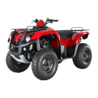
This document is a service manual for the SYM Quad Lander 600 ATV, providing technical data for inspection and repair. It is structured to guide technicians through service procedures, operation key points, and inspection adjustments.
The manual emphasizes safety precautions, including warnings about carbon monoxide from exhaust, the flammability of gasoline, the potential health risks of used engine oil, and the heat of engine components. It also details battery safety, advising against open flames, contact with sulfuric acid, and keeping it out of reach of children. Brake shoe and fluid safety are also covered, recommending vacuum cleaning for brake dust and caution against spilling brake fluid on painted or plastic parts.
The manual stresses the importance of using genuine SYM parts and recommended oils, as well as metric tools for servicing. It advises cleaning parts before removal to prevent contamination and proper storage of complex components. Replacement of gaskets, metal seal rings, O-rings, and split pins after disassembly is mandatory. Proper handling of electrical connections, wire harnesses, and control cables is also highlighted to prevent damage and ensure smooth operation.
Technical Specifications
The Quad Lander 600 (Model UA60A-6) has an overall length of 2110 mm, width of 1150 mm, and height of 1220 mm. Its wheel base is 1300 mm, with a front wheel tread of 900 mm and rear of 895 mm. The dry weight is 345 kg, with a total weight capacity of 420 kg (including a 75 kg passenger). It is powered by a 565cc 4-stroke, water-cooled single-cylinder engine with a bore of 92 mm and stroke of 85 mm. The compression ratio is 10.2.
Key fluid capacities include:
- Fuel Tank: 17000±200 c.c.
- Engine Oil: 3000 c.c. (disassembly), 2400 c.c. (change), 2700 c.c. (with filter change)
- Rear Axle Gear Oil: 100 c.c.
- Front Differential Gear Oil: 200 c.c.
- Coolant: 1750 c.c. (engine + radiator), 350 c.c. (reservoir upper)
The recommended engine oil viscosity is SAE 10W-30 API SG class (KING MATE G-3 oil), and gear oil is SAE 80 or 90 (Bramax HYPOID GEAR OIL #140). The spark plug is an NGK CR8E with a gap of 0.8 mm. Valve clearances are IN: 0.10 ± 0.02 mm and EX: 0.15 ± 0.02 mm. Tire dimensions are AT25x8-12 (front) and AT25x10-12 (rear), with cold tire pressures of 4.8±0.2 psi (front) and 4.1±0.2 psi (rear). The battery is a 12V10Ah (MF battery) type: GTX12-BS.
Usage Features
The ATV features a C.V.T. auto speed change transmission and a full transistor ignition system. It has a speedometer (0-100 km/hr) and a horn (93-112 dB/A). The exhaust system includes a catalytic reaction control system. The maximum speed is above 80 km/hr, and climb ability is below 25°.
Maintenance Features
The manual provides detailed instructions for various maintenance tasks, including:
- Periodical Maintenance Schedule: A comprehensive table outlines inspection, cleaning, adjustment, lubrication, and replacement intervals for various components, ranging from 300 km to 4,000 km or 12 months.
- Lubrication System: Covers engine oil and gear oil replacement, oil strainer cleaning, oil filter unit service, and oil pump inspection and reassembly. Torque values for various bolts are provided.
- Fuel System: Details carburetor removal/installation, air cut-off valve service, vacuum chamber and float chamber disassembly/inspection, and fuel level checking.
- Engine Removal/Installation: Step-by-step guide for removing and installing the engine, including disconnecting electrical components, exhaust, and coolant pipes.
- Cylinder Head/Valve: Instructions for cylinder head removal, inspection (including cam lobe height, rocker arm, valve spring free length, valve stem, and valve guide), valve stem replacement, valve seat inspection/service, and cylinder head reassembly/installation. Valve clearance adjustment is a critical procedure.
- Cylinder/Piston: Covers cylinder and piston removal, inspection (including cylinder warp, piston ring clearance, piston pin diameter, and piston outer diameter), piston ring installation, and cylinder installation.
- V-Belt Driving System: Details left crankcase cover removal/installation, drive belt inspection/replacement, drive plate service, movable drive face disassembly/inspection/reassembly, and driven pulley disassembly/inspection/installation.
- Transmission: Covers transmission disassembly, inspection (shift spindle, shift drum, shift fork, counter shaft, final shaft, gears, and bearings), bearing replacement, and transmission reassembly.
- Wheel Drive Shaft/Propeller Shaft: Instructions for wheel drive shaft removal/disassembly/inspection/assembly, repair pack usage, and propeller shaft removal/disassembly/inspection/installation.
- Cooling System: Includes system test for filler cap and leakage, coolant change, radiator inspection/removal, cooling fan disassembly/assembly, water pump service (seal inspection, removal, bearing installation, impeller installation), and thermostat inspection/removal/installation.
- Body Cover: Provides a sequence for disassembling and assembling various body covers, including front carrier, fuel tank cover, front fender, footrest, rear carrier, and rear fender.
- Front Brake & Front Wheel: Covers brake fluid adding/replacement/air-bleeding, front brake caliper service, brake disk inspection, front brake master cylinder service, front wheel removal/installation, and front wheel hub service.
- Steering/Front Suspension: Instructions for steering handle removal, steering shaft service, steering tie-rod inspection/installation, knuckle disassembly/assembly/inspection, front cushion service, suspension arm service, and toe-in adjustment.
- Rear Brake & Rear Wheel & Rear Cushion: Similar to the front brake section, covering rear wheel removal/installation, rear wheel connecter service, rear wheel hub disassembly/assembly/inspection, rear cushion service, suspension arm service, disk brake system inspection, adding brake fluid, brake fluid replacement/air-bleed, rear brake caliper service, brake disk inspection, and rear brake master cylinder service.
- Electrical System: Provides maintenance data and technical specifications for the charging and ignition systems. It includes trouble diagnosis, battery removal/voltage check/charging, current leakage inspection, regulator rectifier inspection, ignition coil inspection/replacement, pulse generator inspection, starting system circuit diagram, starter relay inspection, starter motor removal/installation, meters removal, light/bulb replacement (headlight, front winker, position light, taillight, rear winker), and switch/horn inspection.
- Electrical Diagram: A detailed wiring diagram is provided for electrical troubleshooting.