Home
Sym
Offroad Vehicle
Quad Lander 600
Page 131 (Repair Pack)
Sym Quad Lander 600 - Repair Pack
246 pages
Manual
Save Page as PDF
To Next Page
To Next Page
To Previous Page
To Previous Page
Loading...
10. WHEEL
DRIVE SHAFT/PROPELLER SHAFT
10-8
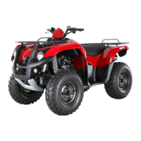
Rep
air Pack
Check if DOJ & UJ boot is damaged
Replace DOJ or UJ assembly if it is damaged.
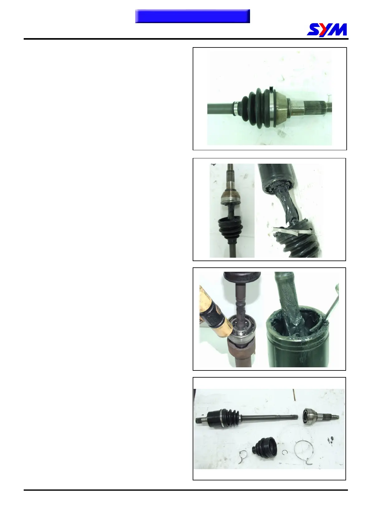
Remove the DOJ & UJ boot.
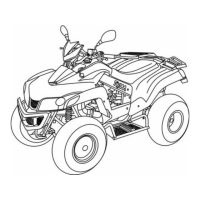
Remove the DOJ & UJ cage.
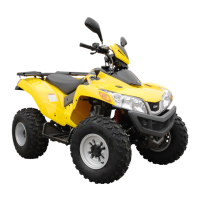
Remove the DOJ & UJ boot.
T
o this chapter content
s
130
132
Table of Contents
Main Page
General Information
16
Table of Contents
16
Maintenance Information
23
Periodical Maintenance Schedule
24
Acceleration Operation
25
Air Cleaner
25
Fuel Lines
25
Spark Plug
26
Valve Clearance
26
Carburetor Idle Speed Adjustment
27
Cylinder Compression Pressure
28
Ignition System
28
Drive Belt
29
Propeller Shaft
29
Front Differential
30
Rear Axle Gearbox
30
Brake System
31
Brake Light Switch
32
Cushion
33
Headlight Beam Distance
33
Nuts, Bolts Tightness
34
Steering Handle
34
Wheel/Tire
34
Special Tools List
35
Mechanism Diagram
40
Precautions in Operation
42
Troubleshooting
42
Engine Oil
43
Engine Oil Strainer Clean
43
Oil Filter Unit
44
Oil Pump
45
Fuel System
49
Precautions in Operation
50
Trouble Diagnosis
51
Carburetor Removal / Installation
52
Air Cut-Off Valve
53
Vacuum Chamber
54
Float Chamber
55
Adjustment of Idle Speed
57
Fuel Tank
58
Air Cleaner
59
Mechanism Diagram
68
Precautions in Operation
69
Troubleshooting
70
Cylinder Head Removal
71
Cylinder Head Inspection
74
Valve Stem Replacement
77
Valve Seat Inspection and Service
78
Cylinder Head Reassembly
80
Cylinder Head Installation
81
Valve Clearance Adjustment
83
Mechanism Diagram
85
Precautions in Operation
86
Trouble Diagnosis
86
Cylinder and Piston Removal
87
Piston Ring Installation
90
Cylinder Installation
91
Piston Installation
91
V-Belt Driving System
93
Maintenance Description
94
Trouble Diagnosis
94
Drive Belt
95
Left Crankcase Cover
95
Drive Plate
96
Movable Drive Face Disassembly
98
Driven Pulley Disassembly
105
Mechanism Diagram
110
Precautions in Operation
111
Trouble Diagnosis
111
Transmission Disassembly
112
Transmission Inspection
116
Bearing Replacement
118
Transmission
121
Transmission Reassembly
121
Wheel Drive Shaft/Propeller Shaft
124
Trouble Diagnosis
125
Wheel Drive Shaft Removal
126
Wheel Drive Shaft Disassembly
127
Wheel Drive Shaft Inspection
130
Repair Pack
131
Wheel Drive Shaft Assembly
133
Front and Rear Propeller Shaft
137
Home Page 11. A.C. Generator/St Arting Clutch
140
Precautions in Operation
141
A.C. Generator Removal
142
Right Crankcase Cover Removal
142
Flywheel Removal
143
Starter One-Way Clutch Removal
143
Recoil Starter Cover Removal
144
Starter One-Way Clutch Installation
145
Flywheel Installation
146
A.C. Generator Installation
147
Right Crankcase Cover Installation
147
Home Page 12. Crankcase / Crankshaft
150
General Information
151
Trouble Diagnosis
151
Crankcase Disassembly
152
Crankshaft Inspection
154
Crankcase Assembly
155
Mechanism Diagram
158
General Information
159
Trouble Diagnosis
159
Cooling System Troubleshooting
160
System Test
162
Radiator
163
Water Pump
165
Thermostat
170
Mechanism Diagram
172
Maintenance
173
Front Carrier
174
Fuel Tank Cover
174
Front Fender
175
Footrest
176
Rear Carrier
177
Rear Fender
177
Mechanism Diagram
180
Maintenance Description
181
Trouble Diagnosis
182
Front Wheel
183
Front Wheel Hub
183
Disk Brake System Inspection
184
Adding Brake Fluid
185
Brake Fluid Replacement / Air-Bleed
185
Front Brake Caliper
187
Brake Disk
188
Front Brake Master Cylinder
188
Mechanism Diagram
192
Handlebar Upper Holder Bolt
193
Knuckle Nut
193
Precautions in Operation
193
Steering Shaft Holder Bolt
193
Steering Shaft Nut
193
Steering Tie-Rod Nut
193
Tie Rod Lock Nut
193
Trouble Diagnosis
193
Steering Handle
194
Steering Shaft
195
Steering Tie-Rod
197
Knuckle
198
Knuckle Disassembly
199
Knuckle Assembly
200
Front Cushion
202
Suspension Arm
203
Toe-In
204
Mechanism Diagram
205
Brake Hose Bolt
206
Brake Lever Nut
206
Maintenance Description
206
Rear Axle Castle Nut
206
Rear Axle Holder Bolt
206
Rear Wheel Nut
206
Swing Arm Pivot Bolt
206
Trouble Diagnosis
207
Rear Wheel
208
Rear Wheel Connecter
208
Rear Wheel Hub
209
Rear Cushion
213
Suspension Arm
214
Disk Brake System Inspection
215
Adding Brake Fluid
216
Air-Bleed Valve
217
Brake Fluid Replacement / Air-Bleed
217
Rear Brake Caliper
218
Brake Disk
219
Rear Brake Master Cylinder
219
Maintenance Data
225
Technical Specification
225
Trouble Diagnosis
226
Charging System
228
Ignition System
231
Cooling Fan Thermo Switch
242
Related product manuals
Sym Quad Lander 250
223 pages
Sym Quad Lander 300
244 pages
Sym Quad Raider 600
247 pages
Sym QUADLANDER 250
57 pages
Sym Track Runner 200
221 pages