13. COOLING SYSTEM
13-1
Mechanism Diagram ··························13-1
General Information ···························13-2
Trouble Diagnosis ······························13-2
Cooling System Troubleshooting ·····13-3
System Test········································ 13-5
Radiator ·············································· 13-6
Water Pump ········································ 13-8
Thermostat ········································· 13-13
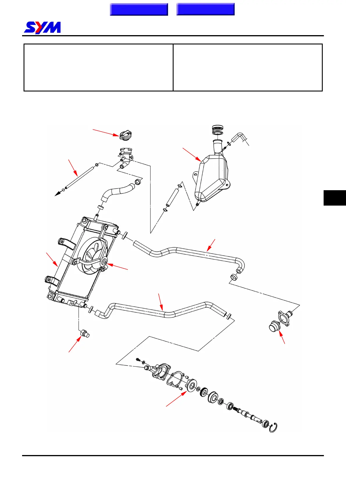
Mechanism Diagram
Radiator filler cap
Radiator
Reserve tank
Thermo switch (fan)
Coolant inlet pipe
Coolant outlet pipe
By-pass pipe
Water pump
Thermostat
13
Cooling fan
Home page Contents
To cylinder head