17. ELECTRICAL SYSTEM
17-16
Switch / Horn
Main Switch
Inspection
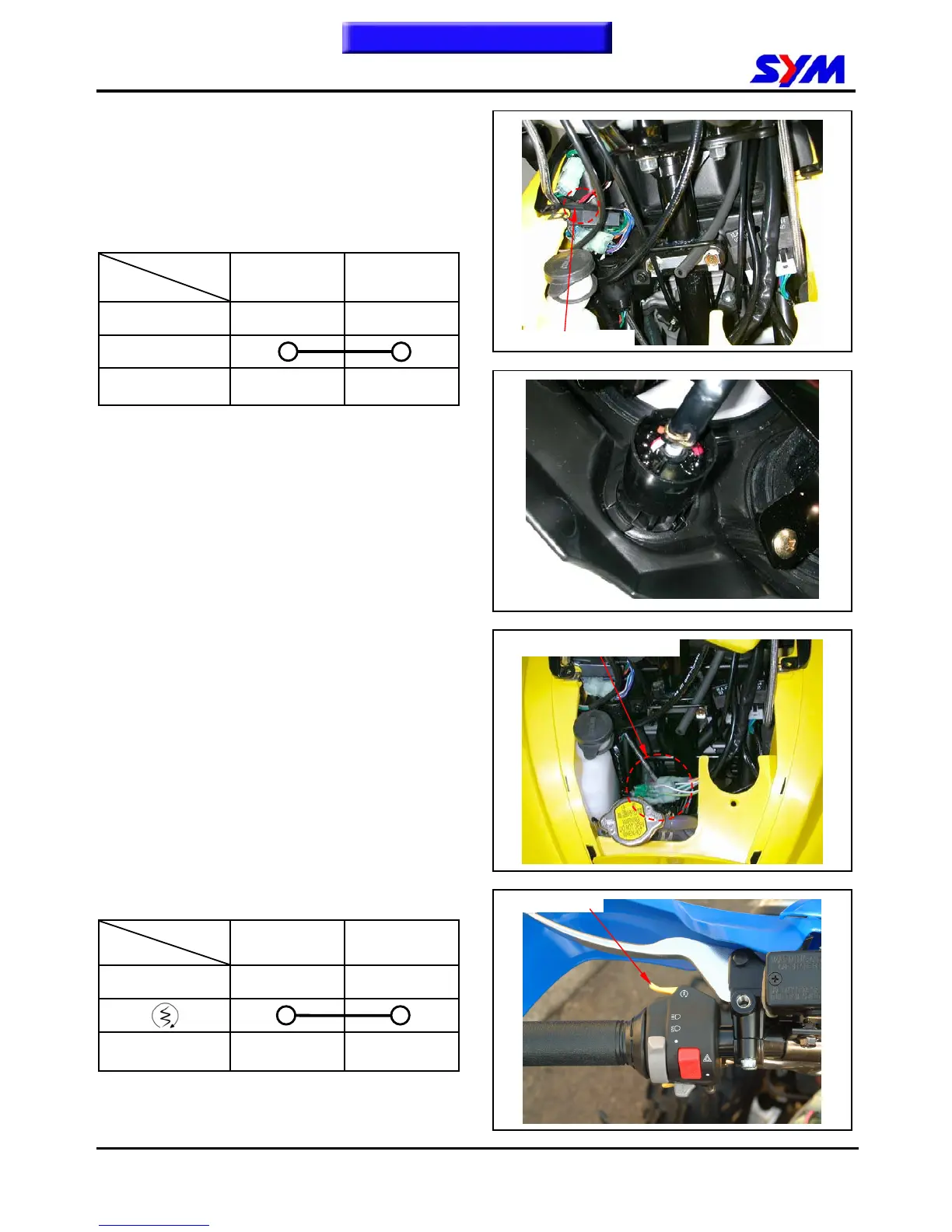
Remove the front center cover.
Disconnect the main switch coupler.
Check the continuity between two points as
indicted below:
Pin
Position
BAT1 BAT2
OFF
ON
Wire Color Red Black
Replacement of main switch
Disconnect the coupler of the main switch.
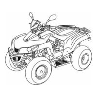
Push out the main switch.
Align the main switch stopper with the meter cover
groove, and install main switch.
Install the main switch coupler.
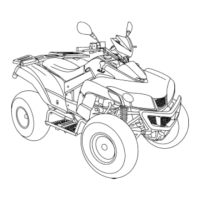
Handle switches
Disconnect the coupler of handle from front fender
left side.
Check the continuity between two points as
indicated in the table below.
Start Switch
Pin
Position
ST SG
FREE
Wire Color
Yellow
/ Red
Yellow
/ Black
To this chapter contents
Headlight switch couplers
Main switch coupler
Start switch