29
4
SYSTEMA EOLO RT rev. 09ENIT04052021
ELECTRICAL CONNECTION
4 ELECTRICAL SYSTEM
The electrical system must be suitable for the maximum power absorbed by the appliance as indicated on the
rating plate and in this manual: the cross-section of the cables must be suitable for the electrical power absorbed.
For any work on the electrical system, refer to the wiring diagrams in this manual.
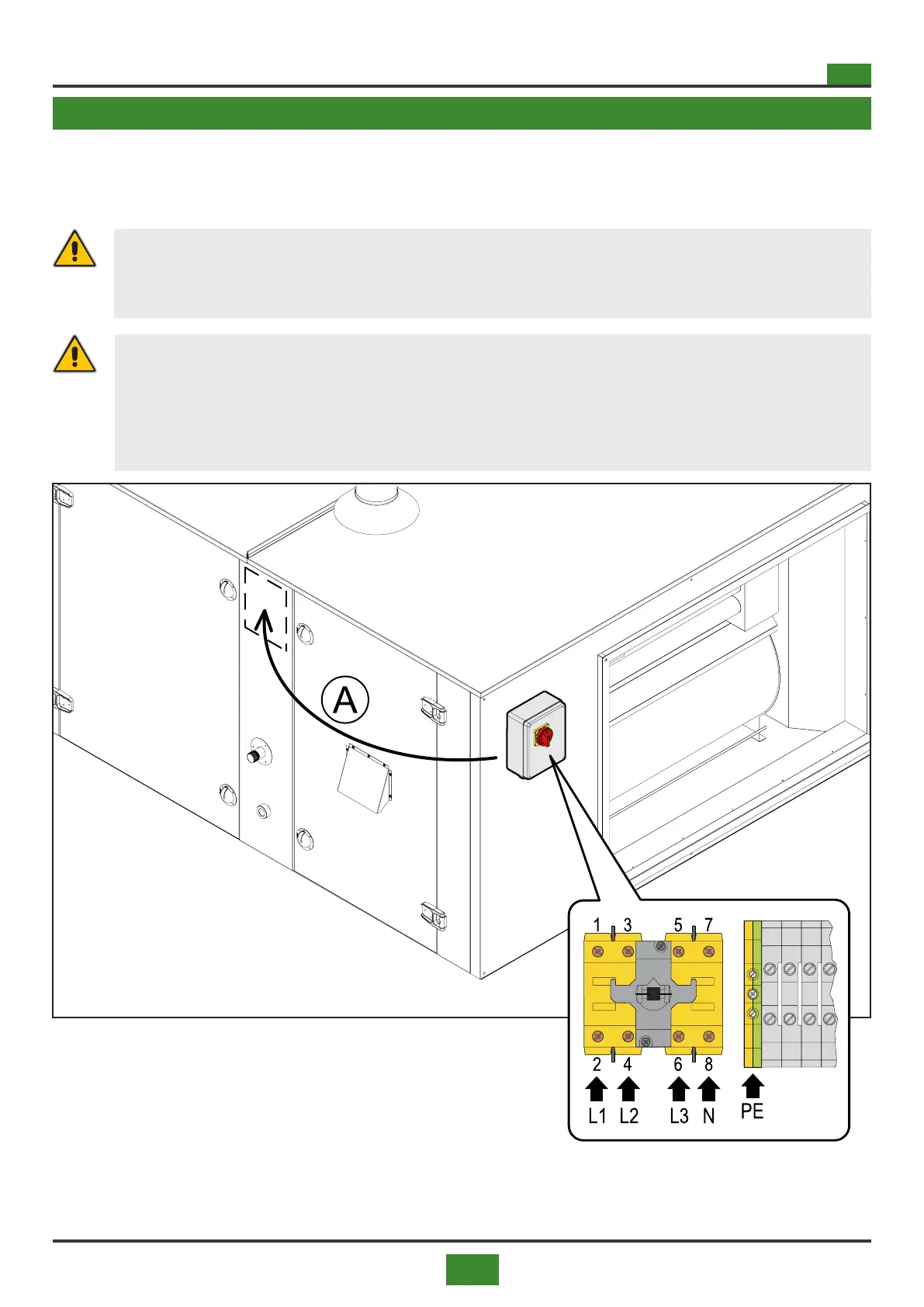
Connect the power supply (3N / PE ~
50Hz 400V) to the isolator located on the
panel on board the thermal unit.
Fig. 4.1 Connecting the power supply
A = In the case of monobloc appliances with the burner
section and the fan section already connected, the
switchboard with switch is placed on the side
WARNING
Electrical connections must be carried out by qualied personnel with the appropriate skills
and in compliance with the relevant national and local regulations in force and with the infor-
mation in this manual instruction.
WARNING
Protect the power supply line upstream, always provide for the use of an omnipolar switch
with an opening between contacts of at least 3 mm.
It is compulsory to connect the appliance to an eective earthing system, taking care to
leave the earth wire slightly longer than the line wires, so that in the event of accidental
disconnection, it is the last one to disconnect, ensuring good earth continuity.