30
4
SYSTEMA EOLO RT rev. 09ENIT04052021
ELECTRICAL CONNECTION
A
B
C
4.1 QUADRI COMANDO PER IL FUNZIONAMENTO DEL BRUCIATORE
4.1.1 Comando manuale con controllo non fornito da Systema
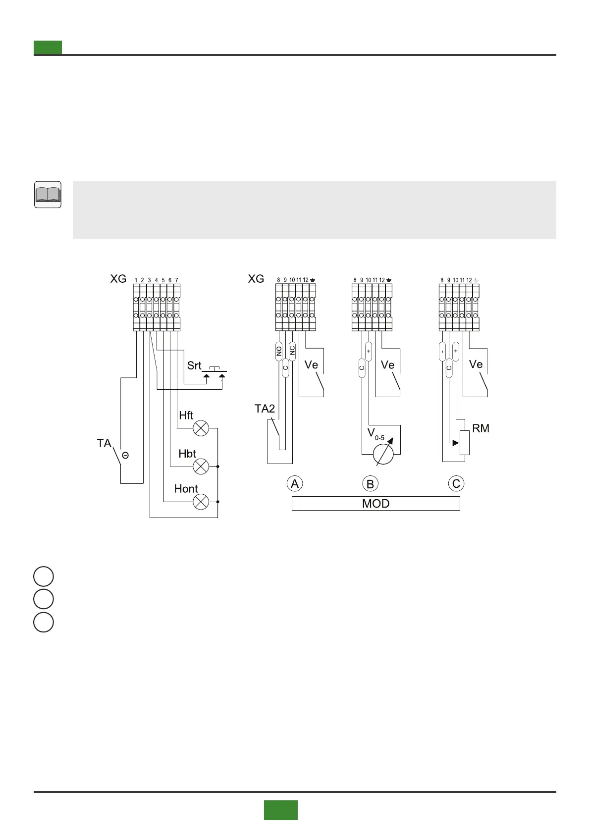
The units can be supplied without a room terminal.
In this case, connect the normally open contact (TA) of the thermostat to terminals 1-2 of the terminal block
(XG) to control the unit (Fig. 4.2).
For manual control of the heat ow, always refer to Figure 4.2 (alternatives A, B and C).
Please note
Operation is 'two-stage' according to parameter Y6 (see tab. 5.3 on p. 56). Setting value 0
(zero) excludes 'two-stage' operation and activates 'one-stage' operation.
Fig 4.2 Room thermostat panel connections and burner power adjustment (optional)
MOD = BURNER POWER ADJUSTMENT
= Two-phase regulation
= Regulation with 0-5 V signal
= Adjustment with 10 kOhm potentiometer
4.1.2 Optional connections (room control panel not supplied by Systema)
Legenda g. 4.2
Hbt = Block signal lamp on grounded panel (not pr ov i de d
by Systema)
Hft = Flame signal lamp on ground panel (not provided by Syste-
ma)
Hont = Luminaire signaling lamp on which ground dro (not
supplied by Systema)
RM = 10 kΩ potentiometer for manual modulation of the
heat capacity (not supplied by Systema)
Srt = Reset button on remote panel - NO contact (neutral)
TA = Room thermostat (not supplied by Systema)
TA2 = Second stage contact of the room thermostat (not
provided by Systema)
V0-5 = 0-5 V signal for automatic door modulation
thermal tata (not supplied by Systema)
Ve = Contact on earthed panel for ventilation activation
summer (not provided by Systema)
XG = Terminal block for connection to the earthed panel
in the housing panel of the main disconnector (see
g. 4.1 on p. 33)