78
9
SYSTEMA EOLO RT rev. 09ENIT04052021
MANUTENZIONE
9.1 FUEL CHANGE
9.1.1 Eolo BC/BL 15÷120 RT
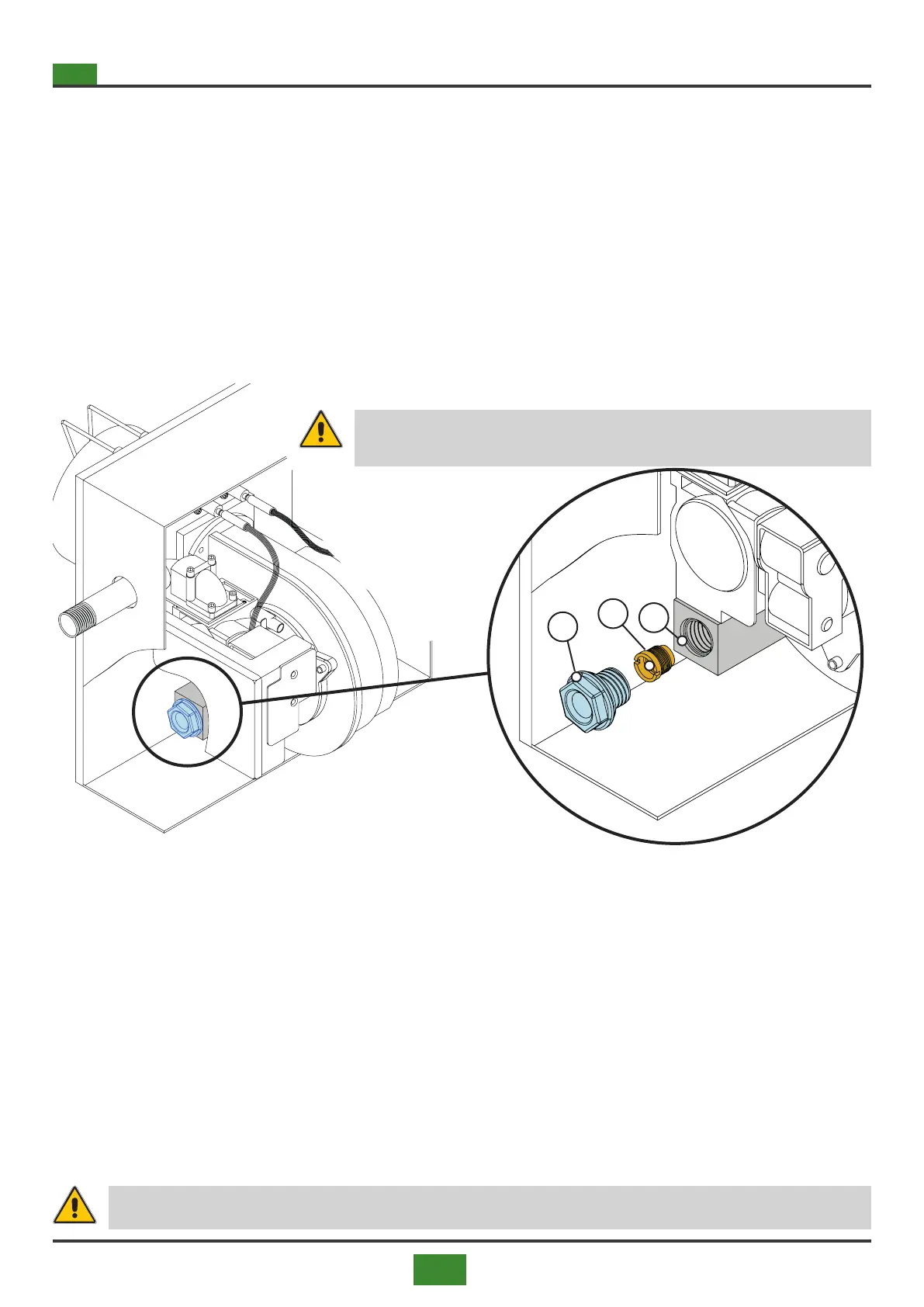
To replace the gas nozzle, follow the procedure below.
1) Shut o the gas and electricity supply.
2) Unscrew the cap (A), g. 9.1, from the nozzle holder tting (C).
3) Unscrew the nozzle (B) located inside the tting (C).
4) Choose the nozzle suitable for the type of gas used, as indicated in tables 8.6 and 8.7 on pages 97 and
99.
5) Screw the nozzle into the housing (C).
6) Screw the cap (A).
7) Start the burner and check the eciency. If any anomalies occur, proceed with the adjustments following
the procedures illustrated in paragraphs 8.3.1 and 8.3.2 on pages 82 and 83
WARNING
Seal the gas valve adjustment part after calibration.
9.1.2 Eolo BC/BL 150÷300 RT
The Eolo models (from the Eolo BC / BL 150 RT model to the Eolo BC / BL 300 RT) are equipped with Premix
burners without nozzles. The air-gas mixing is carried out in the Venturi type mixer with an integrated inlet air
pressure switch. The adequate quantity of gas is aspirated proportionally by the passing air ow. To modify the
type and quantity of the sucked gas, it is necessary to modify the PWM values electronically (see paragraphs
5.1.3 and 5.1.4, pages 56 and 57), by changing the quantity of air passing through the mixer.
By varying the speed of the burner fan, ie by acting electronically on the PWM signal, the quantity of air is
reduced, and consequently the quantity of gas and the heat output of the appliance.
This operation takes place proportionally, therefore the PWM regulation levels for each type of gas correspond
to the value of the burner heat output.
Changing the supply gas pressure does not cause a change in the rated output of the burner.
After changing the type of gas, adjust as described in paragraphs 8.3.4 and 8.3.5 on pages 85 and 86.
WARNING
Seal the gas valve adjustment part after calibration.
Fig.9.1 Nozzle change (Eolo 100, Eolo 120)
A
B
C