33
4
SYSTEMA EOLO RT rev. 09ENIT04052021
ELECTRICAL CONNECTION
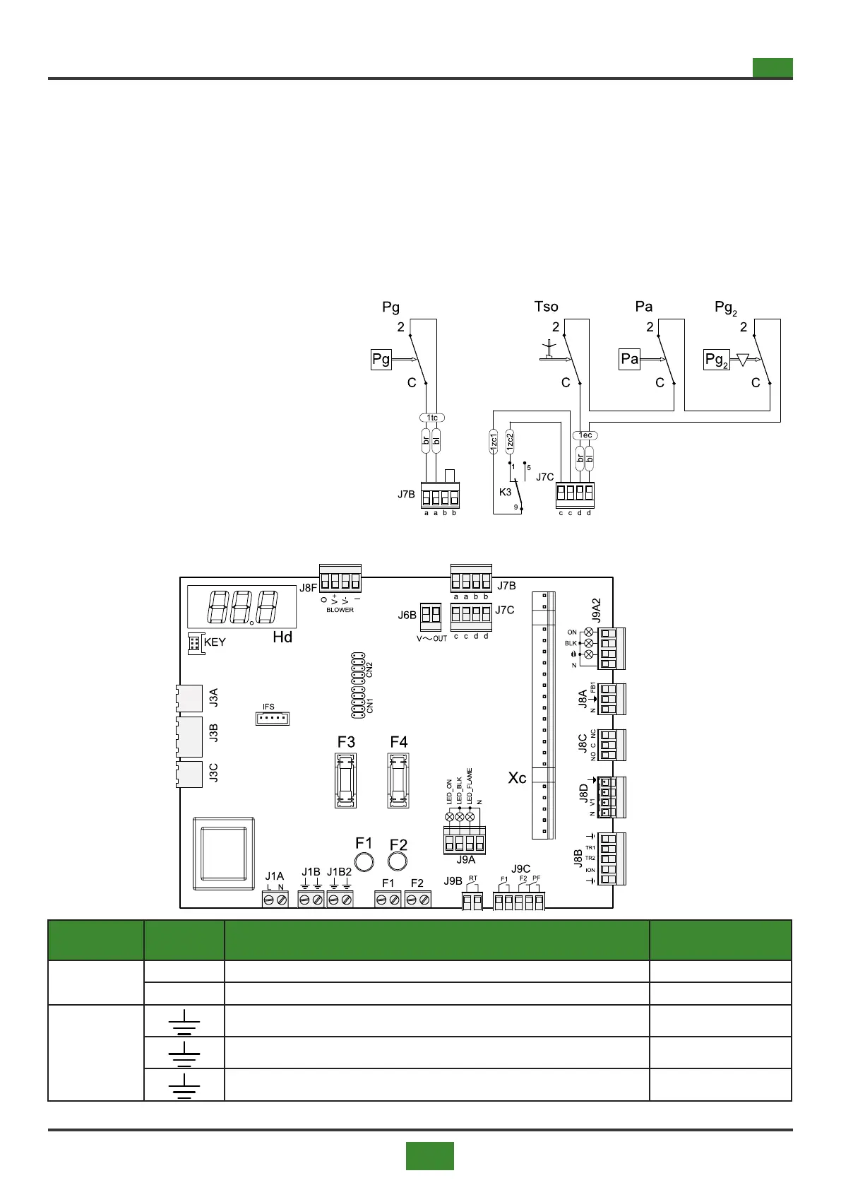
Fig 4.5 Optional components
4.1.5 Optional components
J7B-J7C= Input of mainboard SCP674V130A1
K3 = Contact safety relays
OPTIONAL
Pa = Pressure switch minimum air ow with manual
reset
Pg = Pressure switch minimum gas pressure (standard
for models 150 ÷ 300)
Pg2 = Pressure switch maximum gas pressure with
manual reset (standard for models 120 ÷ 300)
Tso = Safty thermostat - manual reset
4.1.6 Mainboard connections SCP674V130A1
Fig. 4.6 Mainboard
SCP674V130A1
CONNECTOR TERMINAL DESCRIPTION
CONNECTED
COMPONENT
J1A
L Power supply (L) XS-L3 connector
N Power supply (N) XS-N connector
J1B
Ground connection XS connector
Ground connection
Ground connection Em
Tab 4.1 SCP674V130A1 card connections legend (1 of 3)
Continued from p.30
Pp = Button programming (KEY), to be connected only when
programming the board
SCP674V130A1 = Motherboard mod. SCP674V130A1 for
command and control of the appliance
SG = Main switch (see g. 4.1 on page 29)
Sp = Micro switch for switching o the appliance in case of
opening the doors of the fan compartment
Sr. = Button reset - normally open contact (neutral)
Tacc = Transformer ignition
Ts = Thermostat automatic reset safety
Vp = gas blower of premix burner
Xc = Flame control board housing
XG = Terminal block for connection to the earth panel located in
the main switch housing panel (see g. 4.1 on page 29)
XS = Power line terminal located in the burner compartment
XS2 = Terminal board located in the burner housing compartment